Loading...
Showing posts with label Basic. Show all posts

Monday, November 23, 2015

MikroC Programming Guide

PIC Microcontrollers - Programming in C
Microcontroller Programmer

The purpose of this post is to provide basic information that one needs to know in order to be able to use microcontrollers successfully in practice. This post, therefore, doesn’t contain any super interesting program or device schematic with amazing solutions. Instead, the following examples are better proof that program writing is neither a privilege nor a talent issue, but the ability of simply putting puzzle pieces together using directives. Rest assured that design and development of devices mainly consists of the ‘test-correct-repeat’ work. Of course, the more you are in it, the more complicated it gets since the puzzle pieces are put together by both children and first-class architects.

Copyright © 1998–2012. MikroElektronika. All rights reserved. All trade and/or services marks mentioned are the property of their respective owners.

4.0 TABLE OF CONTENTS

Thursday, November 5, 2015

Simple LED Light Meter Circuit - LB1403

Light Meter


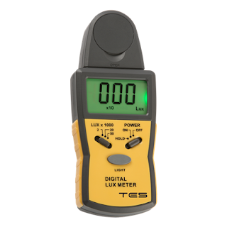
A light meter is a device having a light sensor at one end and a window at the other end which displays the reading that indicates the current light conditions. Light meters are often used in the fields of cinematography, photography and also in test cricket in order to determine the optimum light level for a scene.

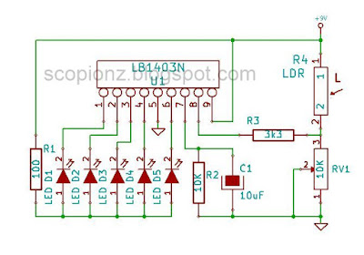
Using LB1403 IC and LDR, we can able to build a cheap light meter. LEDs are used to observe the current light conditions and variable resistor is used for adjust the sensitivity. If the LEDs are too bright, change R1 value (220 - 470 ohms). Supply voltage is 6 - 12V.

Simple LED Light Meter Circuit - LB1403
Light Meter Schematic

Wednesday, November 4, 2015

Simple Automatic Brightness Control Circuit

Automatic Brightness Control

Automatic Brightness Control is the automatic adjustment of the exposure factors such as mA and V. ABC is used to keep the brightness of the display or bulb at a constant level. It involves the adjustment of the V and mA automatically depending on the part of the anatomy being examined. This can be achieved using a LDR, for instance, which monitors the ambient light and change its resistance this resistance changing use to adjust the V, the mA (or both) accordingly.

Automatic Brightness Control Circuit

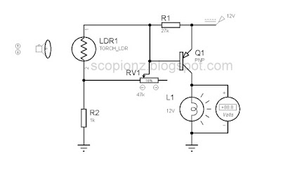
This simple auto brightness adjusting circuit composed with a LDR. The LDR connected with the Base pin of the PNP transistor. By the LDR feature that its resistance changes with the ambient light, the voltage of Base change. When the ambient light is bright, the resistance of LDR is low, and the voltage of Base is reducing and the ambient light is low, the resistance of LDR is high, and the voltage of Base is rising. Then the output voltage of transistor is changing. The variable resistor is use to adjust the sensitivity of circuit. Supply voltage for this circuit is 12v.

Light Dependent Resistors (LDR)


Light Dependent Resistor
A Light Dependent Resistor (LDR) is a resistor that changes in value according to the light falling on it. An LDR commonly has a high resistance in the dark, and a low resistance in the light.

Saturday, May 30, 2015

Stereo Bass Booster Circuit with Simple Mixer

Bass Booster
Bass Booster

A Bass Booster is an audio device, which amplifies the low frequencies (bass) within the audio spectrum. This operates in a similar manner to an audio equalizer. General-purpose equalizers are often not effective at boosting very low frequencies, and therefore many electronics enthusiasts make their own circuit to achieve this purpose. Using following circuit you can boost frequencies below 60Hz.

Stereo Bass Booster circuit
Schematic

This circuit is an active circuit and used TL074, which include separate four op-amps. Alternatively, you can use any general-purpose op amp such as LM324, TL084, etc. This circuit is not only a bass booster it also include a simple mixer circuit. U1A and U1D are act as mixer, U1B and U1C for the base boosting. I design this circuit for electronic switching. Therefor I used two transistors for it. To enable bass boost connect ‘ubb’ to positive supply. You can use normal switch for it. In addition, it is possible to enable bass boost by applying voltage signal to ‘ubb’, which come from a micro-controller or any other source. This circuit can operate in either single supply or dual power supply.

For single power supply
  • Omit C20 and C21.
  • Connect positive supply to VDD and Ground (0v) to GND or VAA.
  • Max Supply voltage is 12v.

For dual power supply
  • Remove J3 (jumper), C15, R19 and R20.
  • Add jumper (0 Ohms) for R20 it.
  • Connect positive supply to VDD, negative for VAA and Ground (0v) to GND.
  • Max Supply voltage is +/-12v.

Please ignore the U2, R21, C16, C18 and P1. Those are not necessary for the operation of this circuit. These parts are optional because that this circuit and PCB were designed for my personal project.

Now connect output of this circuit with amplifier input and give your input to the mixer side. This circuit is ideal for high quality sound. If you want that unique clean high-bass sound then this circuit can provide it.

Schematic and PCB files were added to the download and you can download from it below.

Thursday, August 23, 2012

2 Way AC Flasher

Preview

Schematic
you can change speed by adjusting RV1 

Please be careful! This circuit is directly connected with AC !

Wednesday, August 22, 2012

LED Multivibrator

Preview

Schematic
If you want change speed of blinking then change values of  C1 and C2. increased values of C1,C2 will decrease speed.
Supply Voltage 3-6V

Tuesday, August 21, 2012

LB1403 LED Sound Level Indicator Circuit

LB1403 circuit preview
Preview

This is a another sound level meter circuit using LB1403N. You can use this for any audio system such as Amplifier, Radio, or TV. As well as you can use this either ac level meters such as vu meters or dc level meters such as signal meters.

Features of LB1403N

  • Capable of generating a bar-display for input voltage with 5 LEDs.
  • Operates from either AC or DC input voltage because of on-chip rectifier amplifier.
  • Lighting levels remain stable to line regulation because of on-chip voltage reference.
  • LEDs are driven by a constant current; stable to line regulation.
  • Power supply voltage range is wide (3.5 to 16V), for wide range of applications.
  • SIP-9 pin package and fewer externally connected component result in smaller space requirements on the circuit board.
  • Low noise at LED lighted mode.

For stereo audio systems you need two of this circuit and you can adjust the sound sensitivity by challenging value of RV1.You can directly connect this circuit with output of your amplifier or any other audio system.
Supply voltage for this circuit is 6-12v.

Monday, August 20, 2012

LED Knight Rider Circuits - CD4017 NE555

Everyone like to build LED Knight Rider circuits, specially beginners and little kids. So I will post some knight rider circuits and you can find different pattern of the knight rider circuit from here.

LED Knight Rider 1

Knight Rider Circuits 1 preview
Pattern 1 Preview

Knight Rider Circuits 1
Pattern 1 Circuit

In this circuit LED is running one by one from D1 to D10. after D10, its star from D1 and this will continue until power is disconnected.


LED Knight Rider 2

Knight Rider Circuits 2  preview
Pattern 2 Preview

Knight Rider Circuits 2
Pattern 2 Circuit

In this circuit LED is running two ways. in first step D1, D3, D5, D7 and D9 is light up one by one and the D10, D8, D6, D4 and D2 is light up one by one after D2, its star from D1 and this will continue until power is down. this is more similar to the circuit of Knight Rider TV Series. how ever this circuit doesn't display a tail like circuit in tv series. if you like to add tail then simply add capacitors between every LED. the value of capacitor depend on input voltage and type of LED. so i can't give a value for capacitor. therefor you have to chosen your own value for this by adding different capacitors from 10-220uf. however i think 47-100uf is good for this.


LED Knight Rider 3 - Shadow

Knight Rider Circuits 3 preview
Pattern 3 Preview

Knight Rider Circuits 3
Pattern 3 Circuit

This is the same circuit of pattern 1 and only change the polarity of LED. after power is given all the LED s are light up except D1. next all the LED s are light up except D2. this will continue until D10 off. after that it begin with D1 and this will repeated until power is applied. This method also can applied to the pattern 2. RV1 used to change speed of scrolling. Supply Voltage is 5-12v. Change the R1 resistor to 470-1k when you used power supply above 5v.

4017 is a synchronous decimal up counter with decimal-decoder. it count when the signal is applied to the CLK (pin 14).

The NE555 is a highly stable device for generating accurate time delays or oscillation and used to generate clock pulses for 4017.

Saturday, August 18, 2012

7 Band Spectrum Analyzer Circuit using OP Amps

Spectrum Analyzer
Spectrum Analyzer

Spectrum Analyzer circuit
Circuit Preview

You can use this circuit for build your own spectrum analyzer for amplifier or any audio equipments.

In this post i will not show the sound level meter circuit and this is only the circuit of the band pass filter for the analyzer. you need to connect outputs of this circuit with sound level indicator circuits such as LB1403 , AN6877 to get full circuit. you need totally 8 of sound level indicator circuits. the last bar show the sound level and if you doesn't like it you can omitted that one and then you need totally 7 of sound level indicator circuits.

For build seven band pass filter here I used LA6458S. but you can use any operational amplifier for this. If you use operational amplifier such as LM324 or TL084 then you need only two ICs for this. because those ICs include four different operational amplifiers and LA6458S include only two operational amplifiers.

By using this circuit you can be able to get 50Hz, 100Hz, 330Hz, 1kHz, 3.3kHz, 6.3kHz and 12.5kHz output and these out put can be directly connected with any audio level meter circuit mentioned earlier.

Couple of year ago I found this circuit from a radio and then I build this one and it worked great..!
Supply voltage for this circuit is 12v.

AN6877 - AN6878 LED VU Meter Circuit

AN6877 VU Meter circuit
Preview

This is a sound level meter circuit based on AN6877 and AN6878 series. you can use this for any audio system such as Amplifier, Radio, or TV.

The AN6877 and AN6878 are monolithic integrated circuit driving 7 LED s. The AN6877 respond linearly and the AN6878 does logarithmically for input signal. As output current adjusting pin is set, it can control LED brightness. (by changing value of Rc)

Features  

  • 7 LED bar graph display drive
  • Linear (AN6877) and Logarithm (AN6878) response
  • Adjustable Brightness
  • High output current (25mA)

For stereo system you need two of this circuit and you can adjust sound sensitivity by challenging the value of RV1.
Supply voltage for this circuit is 6-12v.

Friday, August 17, 2012

Simple Light Sensor Circuit

Light Sensor preview
Preview

If you need to turn on any device at morning, then you can use this circuit.

This is a light sensor and you can control any device by connecting it through the relay. The relay was activated when the around is light or when we focus a light to the surface of the LDR.The circuit is very simple and you can use a dot board to assemble it and use any power supply to give power.

If you have a 9v or 6v relay then decrease the input voltage according to the voltage of relay. Use
RV1 to change the sensitivity of this circuit.

Light Sensor Circuit

Operation

In dark condition impedance of LDR is very high. Q1 transistor is in off state. because bias voltage coming to the base of Q1 is low due to high impedance of LDR.

At light condition impedance of LDR is goes down and therefore voltage of Q1 base is goes high and after it reach its saturation voltage Q1 activated and bias voltage for Q2 is start to going through R1 and Q1. then Q2 activated and also relay was activated.

If you connect you device across the NC and Com pin of relay then you can also use this as dark activated switch.

Simple Dark Sensor Circuit

Dark Sensor preview
Preview

If you need a bulb to light up automatically at night, then you can use this circuit.
This is a dark sensor and you can control any device by connecting it through the relay. The relay was activated when the nearby is dark or when we covered the surface of  the LDR.The circuit is very simple and you can use a dot board to assemble it and use any power supply to give power.

If you have a 9v or 6v relay then decrease the input voltage according to the voltage of relay. Use RV1 to change the sensitivity of this circuit.

Dark Sensor Circuit
Dark Sensor Circuit

Operation

In normal condition impedance of LDR is low. Q1 transistor is in off state. because bias voltage coming through R2 and RV1 was grounded through the LDR.

At dark state impedance of LDR is increase and therefore voltage of Q1 base goes high and after it reach ~0.5-0.7v Q1 activated and bias voltage for Q2 is start to going through R1 and Q1. then Q2 activated and also relay was activated.

If you connect you device across the NC and Com pin of relay then you can also use this as light activated switch.

Wednesday, August 1, 2012

JDM - A Simple PIC Programmer Circuit

Circuit circuit on dot Board
Circuit on dot Board

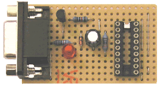
The JDM programmer is one of the simplest PIC programmers available. The design comes from the excellent JDM low cost programmer. It connects direct to the PC serial port using Windows driver software IC-Prog for easy programming. No external power supply is required and a simple board layout is given requiring no special PCB manufacture. Note that the design is limited to the PIC series (12F, 16F and 18F) of chips and cannot be used for In System Programming - ISP.
If you need a more advanced programmer then try WinPic800.

The JDM circuit connects to the computers serial port through a DB9F female connector and the LED are optional but are very useful particularly when testing the circuit.

JDm Circuit 1
Connection with 16F84

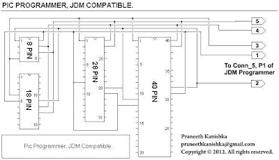
By connecting below two circuits together, you can able to get a complete JDM programmer for program all pic series.

JDm Circuit 2
Circuit 1

JDM all pic series connector
Circuit 2

Hardware Testing

  1. Connect the programmer to the PC serial port using the Female to Male serial lead
  2. Start the IC-Prog software and under 'Settings -Hardware' select JDM Programmer
  3. Insert the PIC into the programming socket

IC-Prog interface
IC-Prog interface

WinPic800 interface
WinPic800 interface


on line

Labels

Recent comment

Visitors

Free counters!
Copyright © 2012 - Scorpionz™.,All rights reserved | Powered by Blogger