Loading...
Showing posts with label Programmer. Show all posts

Tuesday, May 5, 2020

OProg - Open Source USB Programmer - 18F2550

Recently I found a programmer from internet. This programmer is completely free and open source. It used few components and working well. I make some changes to it. You can find the original one from here.

OPROG Prototype
Prototype

Advantages of this programmer are;
  • Completely free and Open Source (including firmware)
  • Programs PIC, dsPIC, ATMEL, EEPROM (I2C, SPI, MicroWire, OneWire, UNIO)
  • Can work as ICD debugger
  • USB 2.0 Full Speed interface
  • Self-powered
  • Doesn't need drivers
  • Hardware generated timings for maximum speed and reliability (writes an 18F2550 in 15s)
  • Open source control programs for Linux and Windows

OPROG diagram
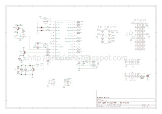
Schematic

Main controller is PIC18F2550, and Supply directly get from PC USB port. HEX, PCB, Schematic and PC software can download from below. And for latest updates and full description please follow the Open Programmer site.


Friday, April 3, 2015

USB HID Bootloader Circuit - 18F4550

Update:

28/11/2015
If you are use mikroC PRO, then tick the Long Hex format in output settings and rename the generated hex file to scp.hex. Finally run mod.exe. It will generate new hex file (mod.hex) and use it with PICDEM software. Otherwise, program may not work correctly.


Boot-loader is a program which helps to program the micro-controller device without using external programmer. It is possible to burn the hex code even if the PC doesn't have a serial port or any other tools.

Required tools for Boot-loader are:
  • USB cable to connect board to the PC
  • A micro controller with already flashed boot loader program

USB HID Bootloader circuit
Boot-loader circuit

The boot-loader starts after Power-On or Reset. The boot-loader checks if pin RE3 is low or high:
  • RE3 = low (0V) : PIC starts in boot-loader mode
  • RE0 = high (5V) : PIC starts user application

Install Boot-loader program

For installing boot-loader program, we need an external programmer. This is a one time process which doesn't need to repeat. Use any programmer like JDM, PicKit, ICD3 to flash the provided boot-loader program USB HID Bootloader.hex.

After successfully programming, connect your device to the PC's USB port (if not already connected). Please make sure that the boot-loader entry condition (RE3 = 0) is fulfilled!

Windows should detect a new USB device. Now open boot-loader PC software and click connect, browse hex file, begin upload.

After finishing upload, click execute. Device will reset automatically and start your program.

Example

void main(); void interrupt() { //-------- interrupt ----------- } void interrupt_low() { } void Vectors() org 0x800 { //-------- remap --------- asm { goto _main //0x800 nop nop goto _interrupt //0x808 nop nop nop nop nop nop goto _interrupt_low //0x818 } } void main() { //----- Main -------- OrgAll(0x800); asm {goto Skip_Vectors} Vectors(); asm {Skip_Vectors:} /* Your Code goes here */ }

Wednesday, August 1, 2012

JDM - A Simple PIC Programmer Circuit

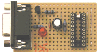
Circuit circuit on dot Board
Circuit on dot Board

The JDM programmer is one of the simplest PIC programmers available. The design comes from the excellent JDM low cost programmer. It connects direct to the PC serial port using Windows driver software IC-Prog for easy programming. No external power supply is required and a simple board layout is given requiring no special PCB manufacture. Note that the design is limited to the PIC series (12F, 16F and 18F) of chips and cannot be used for In System Programming - ISP.
If you need a more advanced programmer then try WinPic800.

The JDM circuit connects to the computers serial port through a DB9F female connector and the LED are optional but are very useful particularly when testing the circuit.

JDm Circuit 1
Connection with 16F84

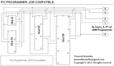
By connecting below two circuits together, you can able to get a complete JDM programmer for program all pic series.

JDm Circuit 2
Circuit 1

JDM all pic series connector
Circuit 2

Hardware Testing

  1. Connect the programmer to the PC serial port using the Female to Male serial lead
  2. Start the IC-Prog software and under 'Settings -Hardware' select JDM Programmer
  3. Insert the PIC into the programming socket

IC-Prog interface
IC-Prog interface

WinPic800 interface
WinPic800 interface


on line

Labels

Recent comment

Visitors

Free counters!
Copyright © 2012 - Scorpionz™.,All rights reserved | Powered by Blogger