Loading...
Showing posts with label 12F. Show all posts

Wednesday, January 2, 2019

Rotary Encoder Decoder Circuit - PIC12F683 Microcontroller

   Recently I need a rotary encoder circuit for my amplifier. So I searched the internet and test some circuits and codings I found. But nothing work for me. Some are worked but not accurate. So i decided to build my own.

What Is Rotary Encoder

Typical Rotary Encoder
   A rotary encoder is a special type of switch that converts the motion of the switch (clockwise or counterclockwise) into an output signal that can be used to determine what direction the knob is being rotated. There are many different types of rotary encoders which use different technologies and construction materials, however, today we’ll be looking specifically at quadrature rotary encoders which are the most common for general electronics. They're used in many applications such as the manual volume control or tuning on a car stereo.

   A quadrature rotary encoder is similar to a potentiometer, however, a rotary encoder doesn’t have limiting points in the rotation; it will rotate infinitely in either direction. Quadrature rotary encoders don’t output an absolute, fixed position, but rather have a number of increments per 360 degrees, and each increment consists of digital pulses known as ‘grey code’. Most encoders have detents which give tactile feedback every time they increment, however, you can also get smooth encoders without detents, usually with a higher number of steps per rotation.

How do They Work?
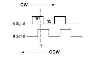
Quadrature Output Table
   It has three pins: A, C, and B. C is the common ground for A and B. A and B are the signal pins. When you rotate the knob, A and B come into contact with the common ground pin, in a particular order depending on the direction you are rotating the knob. When each pin comes into contact with the common ground, they produce a signal. These signals are shifted out of phase with each other as one pin connects before the other pin. This is called quadrature encoding. You need to listen to those pins and the way they pulse in order to determine the direction and number of steps.

The Circuit

   In my circuit I used PIC12F683 microcontroller. It configured to run using its internal oscillater at 8Mhz and internal pull up enable for GP1. And used few components. 0.47uf capacitor used to avoid noices making by rotary encoder. GP0 indicate rotation and GP4 and 5 indicate direction.

Rotary Encoder Circuit

The Coding

   The code was written by using Mikroc Pro for pic.

/**************************************************************************

Rotary Encoder
Copyright (C) 2019 Scorpionz

This program is free software: you can redistribute it and/or modify
it under the terms of the GNU General Public License as published by
the Free Software Foundation, either version 3 of the License, or
(at your option) any later version.

This program is distributed in the hope that it will be useful,
but WITHOUT ANY WARRANTY; without even the implied warranty of
MERCHANTABILITY or FITNESS FOR A PARTICULAR PURPOSE. See the
GNU General Public License for more details.

You should have received a copy of the GNU General Public License
along with this program.

>> Email: scorpionzblog@gmail.com
>> Blog : scopionz.blogspot.com

***************************************************************************/

#define SW       GPIO.F1

void Interrupt()
{

INTCON.GIE = 0;   //Disable Global Interupt
  if(INTCON.INTF)  //RB0/INT External Interrupt Flag bit is set
    {
     if(SW) GPIO.F4=1;
     else   GPIO.F5=1;
     GPIO.F0=1;
     delay_ms(100);
     GPIO   = 0;
    }
INTCON.INTF = 0; //Clear RB0/INT External Interrupt Flag bit
INTCON.GIE = 1;  //Enable Global Interrupt
}

void main()
{
OSCCON = 0x75;
ADCON0 = 0x00;
CMCON0 = 0x07; // Disable Comparators
CMCON1 = 0x00;
ANSEL  = 0x00;

INTCON.GIE = 1; // Global Interrupt Enable
INTCON.INTE = 1; // RB0/INT External Interrupt Enable bit
OPTION_REG = 0b00111111; // wpu & int fall

TRISIO = 0b00000110;
WPU = 0b00000010;
GPIO   = 0b00000001;
delay_ms(500);
GPIO   = 0;
}

Sunday, September 20, 2015

Simple Power Guard Circuit - 12F683

Update
2015-10-05 Wrong circuit diagram - Fixed

Power Guard
Power Guard

This is a very simple and accurate power guard circuit. This circuit is useful to guard the electronic or electrical devices from mains transients and spikes. Very high spikes can develop at power on due to sparking in the switch and more serious effects occur when power resumes after a power failure due to high magnetic field in the distribution transformer. This will damage your device permanently. To avoid such damages we can use this circuit.

This circuit used cheap PIC12F683 micro-controller. It controls all the functions of power guard. After power is applied, the green LED starts to blink. This circuit gives a time delay before giving power to the device. Default value is 30 seconds. However, you can change this value. See configuration for more details. After this delay, Green LED turns on permanently. Then Relay activates and connects power to the device.

When the power is abnormal Yellow or Red LED turns on and relay will turn off to protect our device. The Green LED will start to flash again and after delay time it check power status and turn relay on if the voltage is good. Yellow LED indicates low voltage and Red LED indicate high voltage. If all the LEDs are turn on, that indicates firmware error and pleases re-programmed micro-controller.

Simple Power Guard Circuit Diagram
Circuit Diagram v2

Configuration and Calibration 

For this circuit I used 12v step down transformer. Its output use to sense the power condition. Before using, you need to calibrate this circuit for working correctly. In my project, I choose 240v as normal, 260v as high and 200v as low voltage.

Connect multimeter to GP0 and check voltage. if it exceed 5v immediately turn off power and check the component and connections. (Typical value is 3 - 3.5v)

V = [Tp/12] x [(Vdd/1023) x Eeprom val x 4]
Tp = primary voltage

200 = [240/12] x [(5/1023) x Eeprom val x 4]
260 = [240/12] x [(5/1023) x Eeprom val x 4]

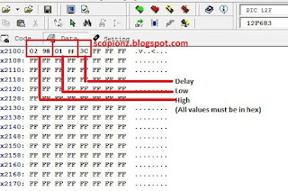
Eeprom value for low condition (200v) = 511 (1FF hex)
GP0 voltage = (2v4)

Eeprom value for high condition (260v) = 664 (298 hex)
GP0 voltage = (3v3)

Write those values to Eeprom.
V high = Eeprom (0)*256 + Eeprom (1) - (0x02 and 0x98)
V low = Eeprom (2)*256 + Eeprom (3) - (0x01 and 0xFF)

Simple Power Guard Eeprom settings
Eeprom settings

To change  delay time simply changes the value of Eeprom address 4 (Default 0x3C)

Delay time in seconds = value of Eeprom address / 2
0 < value of Eeprom address < 255 (0 < Delay time in seconds < 127)
Minimum delay time is 0 seconds and maximum delay time is 2 minutes.

Not for the commercial purpose.

/*************************************************************************** Simple Power Guard Copyright (C) 2014 Praneeth Kanishka This program is free software: you can redistribute it and/or modify it under the terms of the GNU General Public License as published by the Free Software Foundation, either version 3 of the License, or (at your option) any later version. This program is distributed in the hope that it will be useful, but WITHOUT ANY WARRANTY; without even the implied warranty of MERCHANTABILITY or FITNESS FOR A PARTICULAR PURPOSE. See the GNU General Public License for more details. You should have received a copy of the GNU General Public License along with this program. If not, see http://www.gnu.org/licenses >> Email: scorpionzblog@gmail.com >> Web : http://scopionz.blogspot.com ***************************************************************************/ #define L_H GPIO.F1 #define L_L GPIO.F2 #define L_K GPIO.F4 #define RLY GPIO.F5 char idx, del=1, v_d, error; int sense, v_h, v_l; void main() { OSCCON = 0x70; // 8Mhz ADCON0 = 0x00; CMCON0 = 0x07; // Disable Comparators CMCON1 = 0x00; ANSEL = 0x01; TRISIO = 0b00000001; OPTION_REG = 0; WPU=0; Delay_ms(10); GPIO = 0; v_h = Eeprom_Read(1) + Eeprom_Read(0)*256; v_l = Eeprom_Read(3) + Eeprom_Read(2)*256; v_d = Eeprom_Read(4); error = Eeprom_Read(5); if(error>101) error=0; Eeprom_Write(5, error+1); Delay_ms(10); //v_h = 664; //v_l = 511; //v_d = 10; //error = 100; while(1) { if(error>99) { RLY=0; L_K=1; L_H=1; L_L=1; while(1); } if(del) { for(idx=0; idx<v_d; idx++) { //60 = 30sec L_K=~L_K; Delay_ms(500); } del=0; } sense=Adc_Read(0); if(sense>v_h) {RLY=0; L_K=0; L_H=1; del=1;} else if(sense<v_l) {RLY=0; L_K=0; L_L=1; del=1;} else {RLY=1; L_K=1; L_H=0; L_L=0;} Delay_ms(500); } }

Monday, November 10, 2014

Common Remote Control Receiver Circuit (RC5 SIRC NEC) - 16F683

General Remote Controller

The cheapest way to remotely control a device within a visible range is via Infrared light. Almost all audio and video equipment can be controlled this way nowadays. Due to this wide spread use the required components are quite cheap, thus making it ideal for us hobbyists to use IR control for our own projects.

If you ever want to open your gate or run any other device via remote controller you can use this circuit for that. IR remote control receiver for controlling home appliances can be easily made using PIC micro-controller. By using below circuit you can easily control your home appliances using your TV remote, DVD Player remote control or any other remote.

Remote Control Receiver Schematic

The main part of this remote control receiver circuit is PIC16F683. It is cheap and tiny. For infrared receiver I used TSOP1730. However, you can use any other infrared receiver for it (TSOP12xx, TSOP48xx and TSOP62xx product series).

The TSOP1730 used to capture infrared ray from the remote. This infrared receiver changes its output according to the received infrared ray. The output of TSOP1730 then connected to the micro-controller and it decodes the IR signal and gives necessary output according to the IR signal. This circuit is support to Sony, Philips and NEC (I hope, only tested with Sony and Philips) protocols and you can use any remote controller to operate this circuit.

When power is applied, D1 LED will light up. This LED indicates that power is applied. When receiver get IR signal from remote controller then D2 LED light up for 250ms and then off and D3 LED toggle its state. If you need to control heavy load then remove D3 LED and connect transistor and/or relay with this pin. And if you need to switch something like counter then you can used pin 7 (D2 LED) for that.

Sony SIRC Protocol

Sony Protocol
Sony Protocol

The SIRC protocol uses a pulse width encoding of the bits. The pulse representing a logical "1" is a 1.2ms long burst of the 40kHz carrier, while the burst width for a logical "0" is 0.6ms long. All bursts are separated by a 0.6ms long space interval. The recommended carrier duty-cycle is 1/4 or 1/3.

NEC Protocol

NEC Protocol
NEC Protocol

The NEC protocol uses pulse distance encoding of the bits. Each pulse is a 560µs long 38kHz carrier burst (about 21 cycles). A logical "1" takes 2.25ms to transmit, while a logical "0" is only half of that, being 1.125ms. The recommended carrier duty-cycle is 1/4 or 1/3.

Philips RC-5 Protocol

Philips Protocol
Philips Protocol

The protocol uses bi-phase modulation (or so-called Manchester coding) of a 36kHz IR carrier frequency. All bits are of equal length of 1.778ms in this protocol, with half of the bit time filled with a burst of the 36kHz carrier and the other half being idle. A logical zero is represented by a burst in the first half of the bit time. A logical one is represented by a burst in the second half of the bit time. The pulse/pause ratio of the 36kHz carrier frequency is 1/3 or 1/4 which reduces power consumption.

Friday, April 25, 2014

Infrared Remote Control Transmitter and Receiver Circuit - 16F628 12F683

Updated [Sep 14, 2014]
  • Fixed some bugs on IR_Tx.hex
  • Increased Accuracy

This is a general purpose remote control project with 16 channels and using PIC16F628 for transmitter & 12F683 for receiver side. Remote controls usually consist of encoder/decoder parts connected to a transmitter/receiver module which takes care of the transmission of digital signals by radio or infra waves.The transmitter has a varying number of buttons and sends the states of these inputs to the receiver. The receiver device decodes the message and sets the outputs accordingly. To get individual out put from receiver you need to connect 4 to 16 decoder like CD4067, 74HS154 etc or you can use another programming ic. Receiver has two versions. chose better one for your task.
I used Proteus 8 for designing. so if you are already used older version, it is not supported to open this files. All the files can be download from below.

Transmitter Circuit

The TX use 16 pin PIC devices, PIC16F628A is the main part of the transmitter run at 4 MHz crystal. Actually, this device has 4MHz RC internal oscillator but not suitable for use with the project that need critical time as remote control. This ic used to send IR command to receiver. It also generate 38KHz carrier frequency and information bit.

You can use 2xAA size batteries or CR2016 battery or 5v for the circuit. For saving power when use with battery powered we need to increased battery life. Therefore when any keys not pressed within 30 seconds the CPU go to SLEEP mode to reduce battery power consumption and wake-up only when any key pressed. To wake-up the CPU from SLEEP mode the CPU use interrupt on change feature which interrupted when the state on PORTB change, then the program execution after an interrupt is at the interrupt vector, if the global interrupt is not enabled, the program starts executing the first line of code right after the SLEEP instruction.In the interrupt service routine the software will scan the key that pressed and send IR command appropriate with key pressed.

Transmitter circuit
Schematic of Transmitter

Receiver Circuit

The receiver used low cost 8 pin PIC16F683 to control all function of receiver side. The IR was received from TX will demodulated by this ic. When power is applied to circuit the CPU will polling the IR input signal which is the output from IR decoder module (TSOP1736). After IR received the CPU decoding the IR command and then turn on/off appropriate channel.

Ex:
If press 1 on TX then RX out put will be A=1, B=0, C=0, D=0
If press 2 on TX then RX out put will be A=0, B=1, C=0, D=0
If press 16 on TX then RX out put will be A=1, B=1, C=1, D=1

For IR decoder module alternatively you can used TSOP48XX series or any common module.
Connect 4 to 16 decoder with A, B, C and D to get all the out puts.
Supply voltage is 5v (Max).


 Receiver circuit
Schematic of Receiver

PIC12F683 Datasheet
PIC16F628A Datasheet


PIC16F628A pin
Pin Connection

Wednesday, August 1, 2012

JDM - A Simple PIC Programmer Circuit

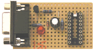
Circuit circuit on dot Board
Circuit on dot Board

The JDM programmer is one of the simplest PIC programmers available. The design comes from the excellent JDM low cost programmer. It connects direct to the PC serial port using Windows driver software IC-Prog for easy programming. No external power supply is required and a simple board layout is given requiring no special PCB manufacture. Note that the design is limited to the PIC series (12F, 16F and 18F) of chips and cannot be used for In System Programming - ISP.
If you need a more advanced programmer then try WinPic800.

The JDM circuit connects to the computers serial port through a DB9F female connector and the LED are optional but are very useful particularly when testing the circuit.

JDm Circuit 1
Connection with 16F84

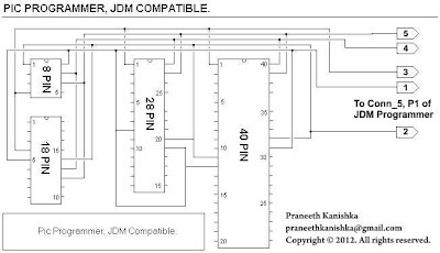
By connecting below two circuits together, you can able to get a complete JDM programmer for program all pic series.

JDm Circuit 2
Circuit 1

JDM all pic series connector
Circuit 2

Hardware Testing

  1. Connect the programmer to the PC serial port using the Female to Male serial lead
  2. Start the IC-Prog software and under 'Settings -Hardware' select JDM Programmer
  3. Insert the PIC into the programming socket

IC-Prog interface
IC-Prog interface

WinPic800 interface
WinPic800 interface


on line

Labels

Recent comment

Visitors

Free counters!
Copyright © 2012 - Scorpionz™.,All rights reserved | Powered by Blogger