Loading...
Showing posts with label Audio. Show all posts

Sunday, November 1, 2020

AN7223 LM7001 PLL FM Stereo Tuner, JQ8400 USB MP3, Bluetooth Audio Player - 16F690

FM USB MP3 Player
Audio Player

This is my new project, 3 in 1 audio player that design for my amplifier. It built in FM radio, USB player and Bluetooth module. Also include a simple mixer with op-amp.

Bottom PCB
Bottom PCB

Top PCB
Top PCB

Side View
Side View

For tuner section I used AN7223 and TA7343 and for PLL here I used LM7001 low cost IC. JQ8400 used for USB function and it controlled by a PIC16F690 microcontroller. U can use any Bluetooth audio module for this. I used MH-M18 Bluetooth module for this.

JQ8400 Module
JQ8400 Module

Bluetooth Module
Bluetooth Module


Please read my previous post for detailed information about PLL FM tuner and jq8400. I wrote a small sample program for control this unit and u can modify it according to your need. Don’t use relay. Just connect I2C directly to R37 & R39.

Control Circuit
Control Circuit

Usage of usb command

// --------- commands ----------------- Write_Df(0x06,0,0); // mp3 next Write_Df(0x05,0,0); // mp3 prev Write_Df(0x02,0,0); // mp3 play Write_Df(0x03,0,0); // mp3 pause Write_Df(0x04,0,0); // mp3 stop Write_Df(0x21,0,0); // mp3 random Write_Df(0xA3,0,5); // mp3 ff 5s Write_Df(0xA2,0,5); // mp3 fr 5s write_Df(0x87,Cur_Tr>>8,Cur_Tr); // mp3 track play (max 9999)

Mikro c source code for Control circuit, source code for PLL FM, Hex file for jq8400 controller and PCB file and circuit are in download section. Hope you like it.


Thursday, August 6, 2020

JQ8400 MP3 Voice Module Microe C code

Previously I wrote a post about well-known voice module of DFPlayer Mini. Today I would like to write a post of advance chip, JQ8400. The main advantages of this chip are;
  • Inquiry of the file name
  • Inquiry of duration of the current audio
  • Inquiry of playback duration
  • Fast backward
  • Fast forward, etc.
jq8400 module
Jq8400 Module

JQ8400 module is a SOC solution that combines a 16bit MCU with an ADSP specialized in audio decoding. By using hardware decoding method, it ensures system stability, quality of sound, and small footprint matching requirements of embedded applications. For the flexibility of R&D, control commands can be sent via one-line mode or RS232 serial communication.
It adopts full duplex serial communication protocol: Baud rate 9600, 8-bit data, no parity and 1 stop bit.

Message Format

Starting Code + Command Code + Data Length + Data 1 – Data n + Checksum
  • Starting Code: fixed as “AA” (in hex)
  • Command Code: 01 – 26 (in hex)
  • Data Length: respective data bytes in commands; length=1 stands for command only, no data.
  • Checksum: The low byte of the sum of all the bytes before the checksum byte.
  • Data format: high 8-bit first, low 8-bit second.

Communication Mechanism

Default power-on state is idle and listening for commands from MCU as a guest The module will not initiate communication and a MCU must take initiative. The TTL level of the serial port is 3.3V. Use a 1K ohm resistor if connecting with a 5V MCU.

jq8400 module pin
Jq8400 Module Pin Details

Code

unsigned short df_wr[] = {0xAA,0,0,0,0,0};
void write_jq_cmd(char cmd, char data_h, char data_l, char len) //jq cmd data {   char m;
  Delay_ms(200);
       df_wr[1]= cmd;
       df_wr[2]= len;
       df_wr[3]= data_h;
       df_wr[4]= data_l;
       df_wr[5]= data_h + data_l + len + df_wr[1] + 0xAA;

    for (m=0; m<6; m++) {      Delay_ms(1);      if(len==0 && m==3) m=5; //(AA 02 00 AC) skip data_h data_l      if(len==1 && m==3) m=4; //(AA 18 01 03 C6) skip data_h      UART1_Write(df_wr[m]);  //aa, cmd, len, dh, dl, sm    }    Delay_ms(10); }

Usage

write_jq_cmd(0x02, 0,0, 0);      //Play write_jq_cmd(0x03, 0,0, 0);      //Pause write_jq_cmd(0x13, 0,27, 1);     //Set volume to 27 write_jq_cmd(0x07, 0x00,0xF4, 2); //Play 244th track write_jq_cmd(0x07, 0x01,0xF4, 2); //Play 500th track write_jq_cmd(0x23, 0x00,0x0A, 2); //FF 10 seconds


Sunday, April 19, 2020

7 Band Real Time Audio Spectrum Analyzer Circuit - 16F819 BA3834S

16F819 Audio Spectrum Analyzer

This is the new version of my previous spectrum analyzer. Used PIC16F819 microcontroller and BA3834 Band-pass filter for spectrum analyzer. It has two versions, BA3834S and BA3834F. Here i used BA3834S. BA3834 are 7-band, band-pass filter ICs that use microprocessor time division to produce serial output for spectrum analyzer displays. To minimize the number of attached components required and enable compact and reliable designs, all of the capacitors for the filters are on the chip. So we can build spectrum analyzer easily

16f819 analizer circuit
Analizer circuit

This circuit included 11 modes (9 patterns, off and random) and it shows which pattern currently running at start-up (S1, S2, etc.). In off mode it shows S0 on display and S+ for random mode. The pattern mode saved to Eeprom to run at next power up. In random mode it changes its pattern in every 3.5 minutes.
PCB, Circuit, and hex available in below

16f819 analizer
16f819 analizer pcb
16f819 analizer pcb


Saturday, February 2, 2019

Uart Controlled DF Player Mikroc Code - 16F628A

  The DFPlayer Mini MP3 Player is a small and low cost MP3 module with an simplified output directly to the speaker. The module can be used as a stand alone module with attached battery, speaker and push buttons or used in combination with a PIC, Arduino or any other with RX/TX capabilities. For this project, I would control the MP3 Player module with a microcontroller and RS232.
DF Player
DF Player

  The DF Player module has all the features which a MP3 player should have. Including advance equalizers, looping and shuffling functions. But here I will show you how to build a simple player with Play/Pause, Next/Preview and vol Up/Down functions. Later you can add more features.

DF Player Pin
DF Player Pin

Specifications:

  • Supported sampling rates (kHz): 8/11.025/12/16/22.05/24/32/44.1/48
  • 24 -bit DAC output, support for dynamic range 90dB , SNR support 85dB
  • Fully supports FAT16 , FAT32 file system, maximum support 32G of the TF card, support 32G of U disk, 64M bytes NORFLASH
  • A variety of control modes, I/O control mode, serial mode, AD button control mode
  • Audio data sorted by folder, supports up to 100 folders, every folder can hold up to 255 songs
  • 30 level adjustable volume
  • 6 -level EQ adjustable
Stand-alone Circuit
Stand-alone Circuit

Circuit:

DF Palyer Circuit
DF Palyer Circuit

In this circuit I used PIC16F628A and its configure to run using its internal oscillator. For sending commands to the PIC i used uart terminal that built in with Mikroc and u need a TTL converter module fo that. Rx pin of df player connected to the PIC's Tx and Rx pin of PIC connected to the TTL converter's Tx.
Rx pin of TTL converter connected to the df player's Tx (optional)

Uart TTL Module
Uart TTL Module
USB TTL Module
USB TTL Module

Connect circuit as above and plug usb or TF card.Then open uart terminal and enter commands as below..
r - Play, s - Pause, n - Next, p - Previous, u - Vol+, d - Vol-.

df palyer connection
Df palyer connection

Circuit in dot board

Code:

This code was written by using mikroC PRO for PIC v6.

/**************************************************************************

DF Player
Copyright (C) 2019 Scorpionz

This program is free software: you can redistribute it and/or modify
it under the terms of the GNU General Public License as published by
the Free Software Foundation, either version 3 of the License, or
(at your option) any later version.

This program is distributed in the hope that it will be useful,
but WITHOUT ANY WARRANTY; without even the implied warranty of
MERCHANTABILITY or FITNESS FOR A PARTICULAR PURPOSE. See the
GNU General Public License for more details.

You should have received a copy of the GNU General Public License
along with this program.

>> Email: scorpionzblog@gmail.com
>> Blog : scopionz.blogspot.com

***************************************************************************/

char df_rd[10], dump, j, u_data;

void Write_Df_Data(char cmd, char data_H, char data_L) //------- df data ----
{
  char m = 0;
  char df_wr[] = {0x7E,0xFF,0x06,0,0,0,0,0xEF};
       df_wr[3]= cmd;
       df_wr[5]= data_H;
       df_wr[6]= data_L;

   Delay_ms(100);
   for (m=0; m<8; m++) UART1_Write(df_wr[m]);
   Delay_ms(300);
}


void interrupt() {   //-------- interrupt --------------------------------------

 if (PIR1.RCIF) {    //------- Usart interrupt ----------
      PIE1.RCIE = 0;
      u_data = UART1_Read();

    if(u_data==0x7E)  {    // check first byte 0x7E
      for (j=1; j<10; j++) { // read next 9 bytes 0xFF, 0x06, 0x03, 0x00, 0x00, 0x01, 0xFE, 0xF7, 0xEF
No:
        if(UART1_Data_Ready()) {    // Check, is data Ready..?
           df_rd[j] = UART1_Read();
           }
          else goto No;
        }
       
        delay_ms(50);
        if(UART1_Data_Ready()) dump = UART1_Read(); //remove duplicate data
      
        if(df_rd[9]==0xEF) { //check last byte 0xEF
         delay_ms(100);
         if(df_rd[3]==0x3C) Write_Df_Data(0x01,0,0); //play next song
         for (j=0; j<10; j++) df_rd[j]=0;            //clear read buffer
        }
      }
     
     else { //------ keyboard commands -------------
            if(u_data=='n') Write_Df_Data(0x01,0,0); //next
            if(u_data=='p') Write_Df_Data(0x02,0,0); //prev
            if(u_data=='u') Write_Df_Data(0x04,0,0); //vol+
            if(u_data=='d') Write_Df_Data(0x05,0,0); //vol-
            if(u_data=='r') Write_Df_Data(0x0D,0,0); //resume
            if(u_data=='s') Write_Df_Data(0x0E,0,0); //stop
           }
    PIE1.RCIE =1;
    PIR1.RCIF =0;
  }
}


void main()
{
 PCON.OSCF = 1;   //4MHz Internal OSC
 CMCON  |= 0x07;  //Disable Comparators

 INTCON.GIE=1;
 INTCON.PEIE=1;
 PIE1.RCIE=1;

 TRISA = 0x00;
 TRISB = 0xFE;  //Tx Rx
 PORTA = 0;
 PORTB = 0;

 Delay_Ms(3000);   // Df initialization 1.5 ~ 3Sec
 UART1_Init(9600);
}


Monday, June 15, 2015

I2C FM Receiver Circuit with LCD - 16F88 BK1080

Digital FM Receiver
Digital FM Receiver


This is a simple stereo FM radio receiver circuit that can scan with 87.5 MHz and 108 MHz seamlessly between 100 kHz step and it use BK1080 as a receiver IC.

Main components of this receiver are a PIC16F88 micro-controller, 16x2 LCD and BK1080 FM receiver chip. This system is design to work with 5V DC power supply. User interface of this system consist with 6 push buttons and a 16×2 character LCD module. All the functions of this receiver can control by this buttons and necessary information displayed on the LCD.

Specifications of this receiver

  • Easy to build
  • Standby mode
  • Automatic gain control
  • Automatic frequency control
  • Automatic noise suppression
  • Preset memory stations up to 250 (default 20)

Schematic of BK1080 I2C FM Receiver
Schematic of BK1080

BK1080

The BK1080 FM receiver employs a low-IF architecture, mixed signal image rejection and all digital demodulation technology. The stations scan of BK1080 searches radio stations based on both the channel RSSI estimation and signal quality assessment, increases the number of receivable stations while avoids false stops. BK1080 enables FM radio reception with low power, small board space and minimum number of external components. All functions controlled through an I2C serial interface. See datasheet for more details.

Numbers of memory locations are determine by the value of Eeprom 1 (default value 0x14).
You can connect an earphone directly with BK1080’s output. However, do not connect speakers directly with IC. I recommended you to use amplifier if you wish to get more sound. In addition, be carefully when soldering BK1080. Because this IC more sensitive to electrostatic. Use DC soldering Iron to solder this IC or unplug your iron when solder. Micro-controller runs using its internal oscillator. RA0 and RA1 are configuring as SCL and SDA. RA2 is not connected. RA6 pin can directly connect with background light of LCD display. As well as it is also can used for the controlling another device like mute pin of power amp.

Selecting the station:
When we are in the power on mode, on the screen we can see "Frq:107.5 Ch:12" - tuned frequency of the station and then the number of the cell where the recorded frequency of the station. Pressing ‘CH_UP’ and ‘CH_DN’ we can move the recorded stations. Pressing ‘FR_UP’ and ‘FR_DN’ we can change the frequency. ‘STORE’ stored the current frequency to the current station and ‘PWR’ used to toggle standby mode and power on mode

Firmware of this system was written by using MikroC for PIC and schematic, hex and Proteus files are available for download.

Saturday, June 13, 2015

PLL Synthesized FM Receiver Circuit with LCD - 16F88 LM7001

FM Tuner
FM Tuner

This is high quality stereo digital PLL synthesized FM radio receiver circuit that can scan with 76 MHz and 108 MHz seamlessly between 100 kHz step, although the sensitivity is high.

Main components of this receiver are a PIC16F88 micro-controller, 16x2 LCD, LM7001 PLL Frequency Synthesizer, AN7223 IF Amp, TA7343 MPX and a FM Tuner. This system is design to work with 12V DC power supply and the LM7805 and 7808 regulators used to manage power requirements to the above-mentioned components.

User interface of this system consist with 6 push buttons and a 16×2 character LCD module. All the functions of this receiver can control by this buttons and necessary information displayed on the LCD.

Specifications of this receiver

  • High sensitivity
  • Standby mode
  • Preset memory stations up to 250 (default 20)
  • 3-user selectable frequency ranges (default 87.5-108)

Schematic of PLL and Power circuit

Schematic of micro-controller and user interrface

LM7001

The LM7001 is a PLL frequency synthesizer LSIs for tuners, making it possible to make up high performance AM/FM tuners easily. These LSIs are software compatible with the LM7000, but do not include an IF calculation circuit. The FM VCO circuit includes a high-speed programmable divider that can divide directly seven reference frequencies. Serial input circuit for data input (using the CE, CL, and DATA pins)

Tuner 

Anticipating the objection that these tuners do not find, I assure you that if you do not be lazy and go through the repair shops where repair radio. In addition, you can get this tuner from old audio system and car set. There are 3 types.

Types of tuner
Types of tuner

  1. FM Front End only (you need to build IF Amp, MPX circuit)
  2. FM Front End with IF (you need to build MPX)
  3. FM Front End IF and MPX

IF Amp and MPX

For IF amp I used AN7223 because it need few external parts and it has high sensitivity and stability. If you cannot find FM quad coil then you can use 2pin 10.7MHZ ceramic resonator for that (see datasheet for more details). However, it is possible to use another IC for this as AN7220, TA7640 and KA2297 etc.

For MPX decoder here I used TA7343. This IC decode mono signal to stereo. This is an optional part. If you wish to work with mono, then omit this part and connect amplifier input with ‘AF’.
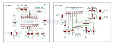
IF and MPX circuit
IF and MPX circuit

Complete circuit pcb
Complete circuit

Operation

Numbers of memory locations are determine by the value of Eeprom 1 (default value 0x14) and frequency range is determine by the value of Eeprom 2 (default value 0x00).
  • If value is 1 then range is 76-108MHz
  • If value is 2 then range is 76-90MHz
  • Else, range is 87.5-108 MHz

Selecting the station:
When we are in the power on mode, on the screen we can see "Frq:106.5 Ch:15" - tuned frequency of the station and then the number of the cell where the recorded frequency of the station. Pressing ‘CH_UP’ and ‘CH_DN’ we can move the recorded stations. Pressing ‘FR_UP’ and ‘FR_DN’ we can change the frequency. ‘STORE’ stored the current frequency to the current station and ‘PWR’ used to toggle standby mode and power on mode

Micro-controller runs using its internal oscillator. RA6 pin can directly connect with background light of LCD display. As well as it is also can used for the controlling another device like mute pin of power amp. For VCC (tuning voltage) you can use up-to 12v.

Firmware of this system was written by using MikroC for PIC and schematic, hex and Proteus files are available for download.

Saturday, May 30, 2015

Stereo Bass Booster Circuit with Simple Mixer

Bass Booster
Bass Booster

A Bass Booster is an audio device, which amplifies the low frequencies (bass) within the audio spectrum. This operates in a similar manner to an audio equalizer. General-purpose equalizers are often not effective at boosting very low frequencies, and therefore many electronics enthusiasts make their own circuit to achieve this purpose. Using following circuit you can boost frequencies below 60Hz.

Stereo Bass Booster circuit
Schematic

This circuit is an active circuit and used TL074, which include separate four op-amps. Alternatively, you can use any general-purpose op amp such as LM324, TL084, etc. This circuit is not only a bass booster it also include a simple mixer circuit. U1A and U1D are act as mixer, U1B and U1C for the base boosting. I design this circuit for electronic switching. Therefor I used two transistors for it. To enable bass boost connect ‘ubb’ to positive supply. You can use normal switch for it. In addition, it is possible to enable bass boost by applying voltage signal to ‘ubb’, which come from a micro-controller or any other source. This circuit can operate in either single supply or dual power supply.

For single power supply
  • Omit C20 and C21.
  • Connect positive supply to VDD and Ground (0v) to GND or VAA.
  • Max Supply voltage is 12v.

For dual power supply
  • Remove J3 (jumper), C15, R19 and R20.
  • Add jumper (0 Ohms) for R20 it.
  • Connect positive supply to VDD, negative for VAA and Ground (0v) to GND.
  • Max Supply voltage is +/-12v.

Please ignore the U2, R21, C16, C18 and P1. Those are not necessary for the operation of this circuit. These parts are optional because that this circuit and PCB were designed for my personal project.

Now connect output of this circuit with amplifier input and give your input to the mixer side. This circuit is ideal for high quality sound. If you want that unique clean high-bass sound then this circuit can provide it.

Schematic and PCB files were added to the download and you can download from it below.

Thursday, May 28, 2015

10 Band I2C Graphic Equalizer Circuit - 16F628 TEA6360

Updated:
  • 2016-08-17 - Added small application for calculate frequencies and parts.

10 Band Equalizer
10 Band Equalizer

A graphic equalizer is a high-fidelity audio control that allows the user to see graphically and control individually a number of different frequency bands in a stereophonic system. A typical graphic equalizer consists of several audio filter/amplifiers, each centered at a specific frequency in the audio range. Most graphic equalizers have two identical sets of filter/amplifiers, one for each channel in a stereophonic system.

The gain controls in most graphic equalizers are slide potentiometers that are adjusted by moving a controller up or down. Gain is increased by sliding the upwards. The slide potentiometers for each channel are placed side-by-side, with the lowest-frequency unit at the left and the highest-frequency unit at the right. In this way, the positions of the buttons appear to follow a graphical curve that represents the gain as a function of frequency for each channel.

By using following circuit you can build a 10 band stereo graphic equalizer that can be controlled via I2C system. For this circuit I used two of TEA6360 ICs. Each IC contains two serial five bands equalizer blocks. Therefore, we need two ICs for 10 bands. We can reduce the size of circuit because all the function can be drive via i2C. So that, we do not need connect potentiometers to control the gain of frequency bands like an ordinary equalizer. In addition, we can reduce cost and complexity of circuit using this IC.

10 Band Equalizer circuit
Schematic

10 Band Equalizer pcb
Circuit on PCB

In my demo code, I used 16F628A micro-controller and single button to set equalizer modes. The modes are ‘Flat’, ’Rock‘, ’Pop‘, ’Jazz‘ and ’Party’. The status will indicate by five LEDs those connected to PORTA. In addition, selected mode saved to device Eeprom and load to ICs when start up. However, according to your choice you can able to change the code.

For example if you need to set gain for each frequency manually, then you can add 1 button to each channel and total 10 buttons. For another example, you can add 3 buttons. One button to raise the gain and other to lower and 3rd one for select desired frequency.

The center frequency of each bands are 31Hz, 62Hz, 125Hz, 250Hz, 500Hz, 1KHz, 2KHz, 4KHz, 8KHz and 16KHz. the Q (quality) factor is 1 to 1.2 and PCB, full schematic and sample code can be downloading in below.

Part List

  • C04, 07, 08, 09 = 0.37uF
  • C10, 11, 12, 13 = 0.18uF
  • C14, 15, 16, 17 = 0.01uF
  • C18, 19, 20, 21 = 0.047uF
  • C22, 23, 24, 25 = 0.022uF
  • C27, 28, 30, 31 = 0.01uF
  • C32, 33, 34, 35 = 0.0052uF
  • C36, 37, 38, 39 = 0.0027uF
  • C40, 41, 42, 43 = 0.0015uF
  • C44, 45, 46, 47 = 720pF

TEA6360

The 5-band stereo equalizer is a 12C-bus controlled tone processor for application in car radio sets, TV sets and music centers. It offers the possibility of sound control as well as equalization of sound pressure behavior of different rooms or loudspeakers, especially in cars.

FEATURES
  • Monolithic integrated 5-band stereo equalizer circuit
  • Five filters for each channel
  • Center frequency, bandwidth and maximum boost/cut defined by external components
  • Choice for variable or constant Q-factor via I2C software
  • Defeat mode
  • All stages are DC-coupled
  • I2C-bus control for all functions
  • Two different module addresses programmable.

Sunday, November 9, 2014

7 Band Real Time Audio Spectrum Analizer Circuit - 16F818 BA3834 MSGEQ7

Audio Spectrum Analyzer

Spectrum analyzers are built in most of the modern signal processing systems for measuring the distribution of signal energy in frequency. An audio spectrum analyzer is used for measurements in the audible frequency spectrum (from 20Hz to 20 kHz) and can be a very powerful tool for keeping a studio well tuned. A Digital, real-time Audio Frequency Spectrum analyzer circuit for audio devices is presented in this project. This circuit aims to professionals or hobbyists who would like to embed it in an audio device or use it as a stand-alone unit. This Digital, real-time Audio Spectrum analyzer circuit for audio devices can be connected to any audio device.

The circuit is based on a PIC16F818 (or PIC16F88) and BA3834S/F (or MSGEQ7).

Audio Spectrum Analyzer circuit
Analyzer with Pattern 1

Operation

The input audio signal is directly connect to the BA3834S/F (or MSGEQ7). The BA3834S/F and MSGEQ7 are 7-band, band-pass filter ICs that use microprocessor time division to produce serial output for spectrum analyzer displays. Those are divides the audio spectrum into seven bands, 63Hz, 160Hz, 400Hz, 1kHz, 2.5kHz, 6.25kHz and 16kHz and out serially from its output pin. That signal then connected to micro-controller. It digitizes and processes this audio signal using an 12-bit ADC module and it computes the distribution of the audio signal energy and displays it on a 7×7 LED display in real time.

Audio Spectrum Analyzer circuit
Analyzer with Pattern 5

After 10 seconds delay this circuit is start to work. User can select display mode by pressing ‘MODE’ button and it support seven display modes. You can use either BA3834S/F or MSGEQ7 as band-pass filter IC and PIC16F88 or PIC16F818 as micro-controller. In my circuit, I used PIC16F818 and BA3834S.
Both versions are available in download section.

Technical details

Display: LED Bar-graphs, 7 Bar-graphs, 49 LEDs, RED Monochrome
Bands: 7 bands
BA3834 - 68, 170, 420 Hz, 1, 2.4, 5.9, 14.4 KHz
MSGEQ7 - 63, 160, 400 Hz, 1, 2.5, 6.25, 16 KHz
Display modes: 7 - user selected
Power Supply requirements: 5V DC

Friday, August 29, 2014

Simple LCD Spectrum Analizer Demo Circuit - 16F628


Spectrum analyzers are widely used within the electronics industry for analyzing the frequency spectrum of radio frequency, RF and audio signals. Looking at the spectrum of a signal, they are able to reveal elements of the signal, and the performance of the circuit producing them that would not be possible using other means.

Audio spectrum analyzer shows you a detailed picture of what you are hearing in real-time, that is, as it happens. You can easily built very cheap spectrum analyzer circuit using below diagram. However, this is not a real-time and it is just a visualizing model. But this work as real one and you can add this to your audio projects to get a nice appearance and add extra value for it.

You can able to download MikroC source and other files from the below link

Simple Spectrum Analizer circuit
Schematic Diagram of Analyzer


on line

Labels

Recent comment

Visitors

Free counters!
Copyright © 2012 - Scorpionz™.,All rights reserved | Powered by Blogger