 |
| FM Tuner |
This is high quality stereo digital PLL synthesized FM radio receiver circuit that can scan with 76 MHz and 108 MHz seamlessly between 100 kHz step, although the sensitivity is high.
Main components of this receiver are a PIC16F88 micro-controller, 16x2 LCD, LM7001 PLL Frequency Synthesizer, AN7223 IF Amp, TA7343 MPX and a FM Tuner. This system is design to work with 12V DC power supply and the LM7805 and 7808 regulators used to manage power requirements to the above-mentioned components.
User interface of this system consist with 6 push buttons and a 16×2 character LCD module. All the functions of this receiver can control by this buttons and necessary information displayed on the LCD.
Specifications of this receiver
- High sensitivity
- Standby mode
- Preset memory stations up to 250 (default 20)
- 3-user selectable frequency ranges (default 87.5-108)
 |
| Schematic of PLL and Power circuit |
 |
| Schematic of micro-controller and user interrface |
LM7001
The LM7001 is a PLL frequency synthesizer LSIs for tuners, making it possible to make up high performance AM/FM tuners easily. These LSIs are software compatible with the LM7000, but do not include an IF calculation circuit. The FM VCO circuit includes a high-speed programmable divider that can divide directly seven reference frequencies. Serial input circuit for data input (using the CE, CL, and DATA pins)
Tuner
Anticipating the objection that these tuners do not find, I assure you that if you do not be lazy and go through the repair shops where repair radio. In addition, you can get this tuner from old audio system and car set. There are 3 types.
 |
| Types of tuner |
- FM Front End only (you need to build IF Amp, MPX circuit)
- FM Front End with IF (you need to build MPX)
- FM Front End IF and MPX
IF Amp and MPX
For IF amp I used AN7223 because it need few external parts and it has high sensitivity and stability. If you cannot find FM quad coil then you can use 2pin 10.7MHZ ceramic resonator for that (see datasheet for more details). However, it is possible to use another IC for this as AN7220, TA7640 and KA2297 etc.
For MPX decoder here I used TA7343. This IC decode mono signal to stereo. This is an optional part. If you wish to work with mono, then omit this part and connect amplifier input with ‘AF’.
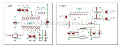 |
| IF and MPX circuit |
 |
| Complete circuit |
Operation
Numbers of memory locations are determine by the value of Eeprom 1 (default value 0x14) and frequency range is determine by the value of Eeprom 2 (default value 0x00).
- If value is 1 then range is 76-108MHz
- If value is 2 then range is 76-90MHz
- Else, range is 87.5-108 MHz
Selecting the station:
When we are in the power on mode, on the screen we can see "Frq:106.5 Ch:15" - tuned frequency of the station and then the number of the cell where the recorded frequency of the station. Pressing ‘CH_UP’ and ‘CH_DN’ we can move the recorded stations. Pressing ‘FR_UP’ and ‘FR_DN’ we can change the frequency. ‘STORE’ stored the current frequency to the current station and ‘PWR’ used to toggle standby mode and power on mode
Micro-controller runs using its internal oscillator. RA6 pin can directly connect with background light of LCD display. As well as it is also can used for the controlling another device like mute pin of power amp. For VCC (tuning voltage) you can use up-to 12v.
Firmware of this system was written by using MikroC for PIC and schematic, hex and Proteus files are available for download.


