Loading...
Showing posts with label USB. Show all posts

Sunday, November 1, 2020

AN7223 LM7001 PLL FM Stereo Tuner, JQ8400 USB MP3, Bluetooth Audio Player - 16F690

FM USB MP3 Player
Audio Player

This is my new project, 3 in 1 audio player that design for my amplifier. It built in FM radio, USB player and Bluetooth module. Also include a simple mixer with op-amp.

Bottom PCB
Bottom PCB

Top PCB
Top PCB

Side View
Side View

For tuner section I used AN7223 and TA7343 and for PLL here I used LM7001 low cost IC. JQ8400 used for USB function and it controlled by a PIC16F690 microcontroller. U can use any Bluetooth audio module for this. I used MH-M18 Bluetooth module for this.

JQ8400 Module
JQ8400 Module

Bluetooth Module
Bluetooth Module


Please read my previous post for detailed information about PLL FM tuner and jq8400. I wrote a small sample program for control this unit and u can modify it according to your need. Don’t use relay. Just connect I2C directly to R37 & R39.

Control Circuit
Control Circuit

Usage of usb command

// --------- commands ----------------- Write_Df(0x06,0,0); // mp3 next Write_Df(0x05,0,0); // mp3 prev Write_Df(0x02,0,0); // mp3 play Write_Df(0x03,0,0); // mp3 pause Write_Df(0x04,0,0); // mp3 stop Write_Df(0x21,0,0); // mp3 random Write_Df(0xA3,0,5); // mp3 ff 5s Write_Df(0xA2,0,5); // mp3 fr 5s write_Df(0x87,Cur_Tr>>8,Cur_Tr); // mp3 track play (max 9999)

Mikro c source code for Control circuit, source code for PLL FM, Hex file for jq8400 controller and PCB file and circuit are in download section. Hope you like it.


Thursday, August 6, 2020

JQ8400 MP3 Voice Module Microe C code

Previously I wrote a post about well-known voice module of DFPlayer Mini. Today I would like to write a post of advance chip, JQ8400. The main advantages of this chip are;
  • Inquiry of the file name
  • Inquiry of duration of the current audio
  • Inquiry of playback duration
  • Fast backward
  • Fast forward, etc.
jq8400 module
Jq8400 Module

JQ8400 module is a SOC solution that combines a 16bit MCU with an ADSP specialized in audio decoding. By using hardware decoding method, it ensures system stability, quality of sound, and small footprint matching requirements of embedded applications. For the flexibility of R&D, control commands can be sent via one-line mode or RS232 serial communication.
It adopts full duplex serial communication protocol: Baud rate 9600, 8-bit data, no parity and 1 stop bit.

Message Format

Starting Code + Command Code + Data Length + Data 1 – Data n + Checksum
  • Starting Code: fixed as “AA” (in hex)
  • Command Code: 01 – 26 (in hex)
  • Data Length: respective data bytes in commands; length=1 stands for command only, no data.
  • Checksum: The low byte of the sum of all the bytes before the checksum byte.
  • Data format: high 8-bit first, low 8-bit second.

Communication Mechanism

Default power-on state is idle and listening for commands from MCU as a guest The module will not initiate communication and a MCU must take initiative. The TTL level of the serial port is 3.3V. Use a 1K ohm resistor if connecting with a 5V MCU.

jq8400 module pin
Jq8400 Module Pin Details

Code

unsigned short df_wr[] = {0xAA,0,0,0,0,0};
void write_jq_cmd(char cmd, char data_h, char data_l, char len) //jq cmd data {   char m;
  Delay_ms(200);
       df_wr[1]= cmd;
       df_wr[2]= len;
       df_wr[3]= data_h;
       df_wr[4]= data_l;
       df_wr[5]= data_h + data_l + len + df_wr[1] + 0xAA;

    for (m=0; m<6; m++) {      Delay_ms(1);      if(len==0 && m==3) m=5; //(AA 02 00 AC) skip data_h data_l      if(len==1 && m==3) m=4; //(AA 18 01 03 C6) skip data_h      UART1_Write(df_wr[m]);  //aa, cmd, len, dh, dl, sm    }    Delay_ms(10); }

Usage

write_jq_cmd(0x02, 0,0, 0);      //Play write_jq_cmd(0x03, 0,0, 0);      //Pause write_jq_cmd(0x13, 0,27, 1);     //Set volume to 27 write_jq_cmd(0x07, 0x00,0xF4, 2); //Play 244th track write_jq_cmd(0x07, 0x01,0xF4, 2); //Play 500th track write_jq_cmd(0x23, 0x00,0x0A, 2); //FF 10 seconds


Tuesday, May 5, 2020

OProg - Open Source USB Programmer - 18F2550

Recently I found a programmer from internet. This programmer is completely free and open source. It used few components and working well. I make some changes to it. You can find the original one from here.

OPROG Prototype
Prototype

Advantages of this programmer are;
  • Completely free and Open Source (including firmware)
  • Programs PIC, dsPIC, ATMEL, EEPROM (I2C, SPI, MicroWire, OneWire, UNIO)
  • Can work as ICD debugger
  • USB 2.0 Full Speed interface
  • Self-powered
  • Doesn't need drivers
  • Hardware generated timings for maximum speed and reliability (writes an 18F2550 in 15s)
  • Open source control programs for Linux and Windows

OPROG diagram
Schematic

Main controller is PIC18F2550, and Supply directly get from PC USB port. HEX, PCB, Schematic and PC software can download from below. And for latest updates and full description please follow the Open Programmer site.


Saturday, February 2, 2019

Uart Controlled DF Player Mikroc Code - 16F628A

  The DFPlayer Mini MP3 Player is a small and low cost MP3 module with an simplified output directly to the speaker. The module can be used as a stand alone module with attached battery, speaker and push buttons or used in combination with a PIC, Arduino or any other with RX/TX capabilities. For this project, I would control the MP3 Player module with a microcontroller and RS232.
DF Player
DF Player

  The DF Player module has all the features which a MP3 player should have. Including advance equalizers, looping and shuffling functions. But here I will show you how to build a simple player with Play/Pause, Next/Preview and vol Up/Down functions. Later you can add more features.

DF Player Pin
DF Player Pin

Specifications:

  • Supported sampling rates (kHz): 8/11.025/12/16/22.05/24/32/44.1/48
  • 24 -bit DAC output, support for dynamic range 90dB , SNR support 85dB
  • Fully supports FAT16 , FAT32 file system, maximum support 32G of the TF card, support 32G of U disk, 64M bytes NORFLASH
  • A variety of control modes, I/O control mode, serial mode, AD button control mode
  • Audio data sorted by folder, supports up to 100 folders, every folder can hold up to 255 songs
  • 30 level adjustable volume
  • 6 -level EQ adjustable
Stand-alone Circuit
Stand-alone Circuit

Circuit:

DF Palyer Circuit
DF Palyer Circuit

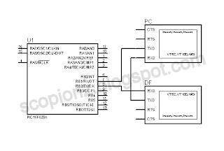
In this circuit I used PIC16F628A and its configure to run using its internal oscillator. For sending commands to the PIC i used uart terminal that built in with Mikroc and u need a TTL converter module fo that. Rx pin of df player connected to the PIC's Tx and Rx pin of PIC connected to the TTL converter's Tx.
Rx pin of TTL converter connected to the df player's Tx (optional)

Uart TTL Module
Uart TTL Module
USB TTL Module
USB TTL Module

Connect circuit as above and plug usb or TF card.Then open uart terminal and enter commands as below..
r - Play, s - Pause, n - Next, p - Previous, u - Vol+, d - Vol-.

df palyer connection
Df palyer connection

Circuit in dot board

Code:

This code was written by using mikroC PRO for PIC v6.

/**************************************************************************

DF Player
Copyright (C) 2019 Scorpionz

This program is free software: you can redistribute it and/or modify
it under the terms of the GNU General Public License as published by
the Free Software Foundation, either version 3 of the License, or
(at your option) any later version.

This program is distributed in the hope that it will be useful,
but WITHOUT ANY WARRANTY; without even the implied warranty of
MERCHANTABILITY or FITNESS FOR A PARTICULAR PURPOSE. See the
GNU General Public License for more details.

You should have received a copy of the GNU General Public License
along with this program.

>> Email: scorpionzblog@gmail.com
>> Blog : scopionz.blogspot.com

***************************************************************************/

char df_rd[10], dump, j, u_data;

void Write_Df_Data(char cmd, char data_H, char data_L) //------- df data ----
{
  char m = 0;
  char df_wr[] = {0x7E,0xFF,0x06,0,0,0,0,0xEF};
       df_wr[3]= cmd;
       df_wr[5]= data_H;
       df_wr[6]= data_L;

   Delay_ms(100);
   for (m=0; m<8; m++) UART1_Write(df_wr[m]);
   Delay_ms(300);
}


void interrupt() {   //-------- interrupt --------------------------------------

 if (PIR1.RCIF) {    //------- Usart interrupt ----------
      PIE1.RCIE = 0;
      u_data = UART1_Read();

    if(u_data==0x7E)  {    // check first byte 0x7E
      for (j=1; j<10; j++) { // read next 9 bytes 0xFF, 0x06, 0x03, 0x00, 0x00, 0x01, 0xFE, 0xF7, 0xEF
No:
        if(UART1_Data_Ready()) {    // Check, is data Ready..?
           df_rd[j] = UART1_Read();
           }
          else goto No;
        }
       
        delay_ms(50);
        if(UART1_Data_Ready()) dump = UART1_Read(); //remove duplicate data
      
        if(df_rd[9]==0xEF) { //check last byte 0xEF
         delay_ms(100);
         if(df_rd[3]==0x3C) Write_Df_Data(0x01,0,0); //play next song
         for (j=0; j<10; j++) df_rd[j]=0;            //clear read buffer
        }
      }
     
     else { //------ keyboard commands -------------
            if(u_data=='n') Write_Df_Data(0x01,0,0); //next
            if(u_data=='p') Write_Df_Data(0x02,0,0); //prev
            if(u_data=='u') Write_Df_Data(0x04,0,0); //vol+
            if(u_data=='d') Write_Df_Data(0x05,0,0); //vol-
            if(u_data=='r') Write_Df_Data(0x0D,0,0); //resume
            if(u_data=='s') Write_Df_Data(0x0E,0,0); //stop
           }
    PIE1.RCIE =1;
    PIR1.RCIF =0;
  }
}


void main()
{
 PCON.OSCF = 1;   //4MHz Internal OSC
 CMCON  |= 0x07;  //Disable Comparators

 INTCON.GIE=1;
 INTCON.PEIE=1;
 PIE1.RCIE=1;

 TRISA = 0x00;
 TRISB = 0xFE;  //Tx Rx
 PORTA = 0;
 PORTB = 0;

 Delay_Ms(3000);   // Df initialization 1.5 ~ 3Sec
 UART1_Init(9600);
}


Sunday, April 12, 2015

USB Controlled 8x40 Dot Matrix Moving Display Circuit - 18F2550

2015-04-12 Initial release
2015-04-16 Wrong Configuration Bits - Fixed


This dot matrix moving display message board will be of five, 8x8 dot matrix, which will be able to display 10 different messages and maximum 60 characters of each. You can set messages by using PC application that created by me using visual basic and those messages will show on matrix display. When the circuit is disconnected form PC then default messages displayed on the display.

USB Controlled 8x40 Dot Matrix Moving Display circuit
Circuit Diagram

PIC18F2550 is the micro-controller and main part of this circuit. This IC used because it has built-in USB transceiver that used to communicate with PC application. PORTB of IC controls the row of Matrices. This PORTB pins then connected to display through the ULN2803 IC, which consists of 8 Darlington arrays. Because micro-controller unable to handle heavy load. In the diagram, you can see 8 NOT gates. These gates used only simulation in Proteus. Therefore, you should replace with these gates with ULN2803 IC. The columns are driven by the outputs of a 40-bit serial-in-parallel-out arrangement constructed by cascading five 74HC595 ICs. The 74HC595 device is an 8-bit serial-input and parallel/serial output shift register. The serial output feature allows cascading of multiple 74HC595 devices. The time format of PC must be in English, otherwise time will not display properly on the display. LED is indicated that whether USB cable connected or not and Scrolling speed of circuit can be change by varying the value of VR1. Supply voltage for this circuit is 5v.

The PC application and other files can be download from below link.

Friday, April 3, 2015

USB HID Bootloader Circuit - 18F4550

Update:

28/11/2015
If you are use mikroC PRO, then tick the Long Hex format in output settings and rename the generated hex file to scp.hex. Finally run mod.exe. It will generate new hex file (mod.hex) and use it with PICDEM software. Otherwise, program may not work correctly.


Boot-loader is a program which helps to program the micro-controller device without using external programmer. It is possible to burn the hex code even if the PC doesn't have a serial port or any other tools.

Required tools for Boot-loader are:
  • USB cable to connect board to the PC
  • A micro controller with already flashed boot loader program

USB HID Bootloader circuit
Boot-loader circuit

The boot-loader starts after Power-On or Reset. The boot-loader checks if pin RE3 is low or high:
  • RE3 = low (0V) : PIC starts in boot-loader mode
  • RE0 = high (5V) : PIC starts user application

Install Boot-loader program

For installing boot-loader program, we need an external programmer. This is a one time process which doesn't need to repeat. Use any programmer like JDM, PicKit, ICD3 to flash the provided boot-loader program USB HID Bootloader.hex.

After successfully programming, connect your device to the PC's USB port (if not already connected). Please make sure that the boot-loader entry condition (RE3 = 0) is fulfilled!

Windows should detect a new USB device. Now open boot-loader PC software and click connect, browse hex file, begin upload.

After finishing upload, click execute. Device will reset automatically and start your program.

Example

void main(); void interrupt() { //-------- interrupt ----------- } void interrupt_low() { } void Vectors() org 0x800 { //-------- remap --------- asm { goto _main //0x800 nop nop goto _interrupt //0x808 nop nop nop nop nop nop goto _interrupt_low //0x818 } } void main() { //----- Main -------- OrgAll(0x800); asm {goto Skip_Vectors} Vectors(); asm {Skip_Vectors:} /* Your Code goes here */ }


on line

Labels

Recent comment

Visitors

Free counters!
Copyright © 2012 - Scorpionz™.,All rights reserved | Powered by Blogger