Loading...
Showing posts with label 18F. Show all posts

Tuesday, May 5, 2020

OProg - Open Source USB Programmer - 18F2550

Recently I found a programmer from internet. This programmer is completely free and open source. It used few components and working well. I make some changes to it. You can find the original one from here.

OPROG Prototype
Prototype

Advantages of this programmer are;
  • Completely free and Open Source (including firmware)
  • Programs PIC, dsPIC, ATMEL, EEPROM (I2C, SPI, MicroWire, OneWire, UNIO)
  • Can work as ICD debugger
  • USB 2.0 Full Speed interface
  • Self-powered
  • Doesn't need drivers
  • Hardware generated timings for maximum speed and reliability (writes an 18F2550 in 15s)
  • Open source control programs for Linux and Windows

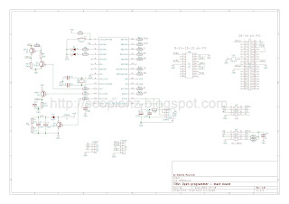
OPROG diagram
Schematic

Main controller is PIC18F2550, and Supply directly get from PC USB port. HEX, PCB, Schematic and PC software can download from below. And for latest updates and full description please follow the Open Programmer site.


Sunday, April 12, 2015

USB Controlled 8x40 Dot Matrix Moving Display Circuit - 18F2550

2015-04-12 Initial release
2015-04-16 Wrong Configuration Bits - Fixed


This dot matrix moving display message board will be of five, 8x8 dot matrix, which will be able to display 10 different messages and maximum 60 characters of each. You can set messages by using PC application that created by me using visual basic and those messages will show on matrix display. When the circuit is disconnected form PC then default messages displayed on the display.

USB Controlled 8x40 Dot Matrix Moving Display circuit
Circuit Diagram

PIC18F2550 is the micro-controller and main part of this circuit. This IC used because it has built-in USB transceiver that used to communicate with PC application. PORTB of IC controls the row of Matrices. This PORTB pins then connected to display through the ULN2803 IC, which consists of 8 Darlington arrays. Because micro-controller unable to handle heavy load. In the diagram, you can see 8 NOT gates. These gates used only simulation in Proteus. Therefore, you should replace with these gates with ULN2803 IC. The columns are driven by the outputs of a 40-bit serial-in-parallel-out arrangement constructed by cascading five 74HC595 ICs. The 74HC595 device is an 8-bit serial-input and parallel/serial output shift register. The serial output feature allows cascading of multiple 74HC595 devices. The time format of PC must be in English, otherwise time will not display properly on the display. LED is indicated that whether USB cable connected or not and Scrolling speed of circuit can be change by varying the value of VR1. Supply voltage for this circuit is 5v.

The PC application and other files can be download from below link.

Friday, April 3, 2015

USB HID Bootloader Circuit - 18F4550

Update:

28/11/2015
If you are use mikroC PRO, then tick the Long Hex format in output settings and rename the generated hex file to scp.hex. Finally run mod.exe. It will generate new hex file (mod.hex) and use it with PICDEM software. Otherwise, program may not work correctly.


Boot-loader is a program which helps to program the micro-controller device without using external programmer. It is possible to burn the hex code even if the PC doesn't have a serial port or any other tools.

Required tools for Boot-loader are:
  • USB cable to connect board to the PC
  • A micro controller with already flashed boot loader program

USB HID Bootloader circuit
Boot-loader circuit

The boot-loader starts after Power-On or Reset. The boot-loader checks if pin RE3 is low or high:
  • RE3 = low (0V) : PIC starts in boot-loader mode
  • RE0 = high (5V) : PIC starts user application

Install Boot-loader program

For installing boot-loader program, we need an external programmer. This is a one time process which doesn't need to repeat. Use any programmer like JDM, PicKit, ICD3 to flash the provided boot-loader program USB HID Bootloader.hex.

After successfully programming, connect your device to the PC's USB port (if not already connected). Please make sure that the boot-loader entry condition (RE3 = 0) is fulfilled!

Windows should detect a new USB device. Now open boot-loader PC software and click connect, browse hex file, begin upload.

After finishing upload, click execute. Device will reset automatically and start your program.

Example

void main(); void interrupt() { //-------- interrupt ----------- } void interrupt_low() { } void Vectors() org 0x800 { //-------- remap --------- asm { goto _main //0x800 nop nop goto _interrupt //0x808 nop nop nop nop nop nop goto _interrupt_low //0x818 } } void main() { //----- Main -------- OrgAll(0x800); asm {goto Skip_Vectors} Vectors(); asm {Skip_Vectors:} /* Your Code goes here */ }

Saturday, January 17, 2015

8x32 LED Matrix Real Time Clock Circuit with Alarm - 18F2550

Most of electronic enthusiasts are very much interest about the LED matrix displays. So if you are one of them this is for you. If you are not familiar with LED matrices at all, please read these two experimental tutorials Basics of LED matrix display and scrolling text message on an LED matrix .

8x32 LED Matrix Clock
LED Matrix Clock

LED matrix displays are very popular in these days and most of people are love it but wonder how it can construct. So that I decide to provide this post for you. This project is about constructing a mono-color LED matrix display based real time clock. It can display time, date, and room temperature alarm with chime function. You can control this clock using four switches (Mode, Enter, Up, Down) and can changed the speed of scrolling by RV2.

8x32 LED Matrix Clock circuit
Matrix Clock

The main IC of this project is PIC16F2550 micro controller which controls all the sections, and display the LED matrix with the help of 74HC595 shift registers and DS1307 RTC IC. As amplifier I chose TDA7052 because of low cost and almost no component. But you can choose any amplifier for it. To react function keys you need to press and hold keys and remember to put 100-330 resistors between shift registers and displays if those are too bright.

This built in some events and according to it clock change its welcome massage and alarm tone.

The events are;
  • New Year – Jan 1  
  • Vesak  - May 
  • Christmas - Dec 25
  • Valentine – Feb 14 and
  • Birthday - User Define

You can add custom date for birthday by changing the values of Eeprom (1) for day and Eeprom (2) for month. Also used hex value for this.
Ex: for Jun 25 -> Eeprom (1) = 19 and Eeprom (2) = 06

LED Matrix Clock Preview

Tested and Working!

Wednesday, August 1, 2012

JDM - A Simple PIC Programmer Circuit

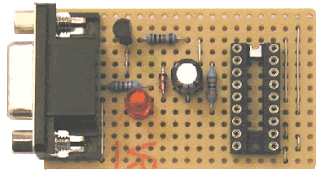
Circuit circuit on dot Board
Circuit on dot Board

The JDM programmer is one of the simplest PIC programmers available. The design comes from the excellent JDM low cost programmer. It connects direct to the PC serial port using Windows driver software IC-Prog for easy programming. No external power supply is required and a simple board layout is given requiring no special PCB manufacture. Note that the design is limited to the PIC series (12F, 16F and 18F) of chips and cannot be used for In System Programming - ISP.
If you need a more advanced programmer then try WinPic800.

The JDM circuit connects to the computers serial port through a DB9F female connector and the LED are optional but are very useful particularly when testing the circuit.

JDm Circuit 1
Connection with 16F84

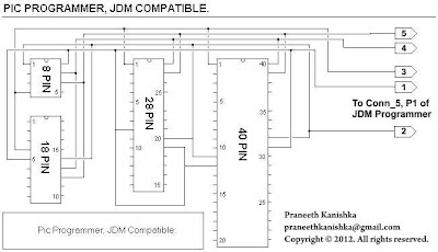
By connecting below two circuits together, you can able to get a complete JDM programmer for program all pic series.

JDm Circuit 2
Circuit 1

JDM all pic series connector
Circuit 2

Hardware Testing

  1. Connect the programmer to the PC serial port using the Female to Male serial lead
  2. Start the IC-Prog software and under 'Settings -Hardware' select JDM Programmer
  3. Insert the PIC into the programming socket

IC-Prog interface
IC-Prog interface

WinPic800 interface
WinPic800 interface

Saturday, July 28, 2012

64x8 LED Matrix Moving Display Circuit - 18F2550

Matrix Display preview
Matrix Display

LED dot matrices are very popular and it can displaying information such as both static and animated text and images. you can see it at gas stations displaying the gas prices, or in the public places and alongside highways, displaying advertisements on large dot matrix panels. In this project, we can use LED dot matrix interface with a micro-controller to display static characters and symbols.

This circuit of a Dot Matrix is based on the PIC18F2550 micro-controller and software is pic basic pro and it also include Proteus ISIS simulation and Kicad PCB files.

Matrix Display pcb
Circuit Board

This circuit has 8 of 8×8 matrices and currently I used only 3 matrices.but you can use up to 8 matrices. I added two different hardware versions in download. but firmware is same. In my circuit I used CD4541 PCB and bypass the transistors. But brightness of your displays are very low or you need extra brightness then used transistors. and remember to add heat sink to regulator ic.

Character Set

The most difficult thing about using the dot matrix LED display is defining the characters. Basically for ASCII characters you need an array of 128 blocks each having 8 column data numbers.
The usual way is to get out a piece of graph paper and define your characters by drawing blocks where a pixel is on. You then translate each line into hex (binary to hex is very easy) and then transfer this information to your program source code.

Theory of LED Dot Matrix Display

In a dot matrix display, multiple LED s are wired together in rows and columns. This is done to minimize the number of pins required to drive them. For example, a 8×8 matrix of LED s would need 64 I/O pins, one for each LED pixel. By wiring all the anodes together in rows , and cathodes in columns, the required number of I/O pins is reduced to 16. Each LED is addressed by its row and column number.Characters can be displayed by fast scanning of either rows or columns.


Video Of Matrix Display

How to compile?

First install MicroCode Studio
Then install PICBASIC PRO Compiler
Finally install MPLAB IDE

Now open MicroCode Studio
Click View >> Compile and Program Option >> Compiler >> Find Automatically
Else you can manually search your pbp folder (Default C:\pbp)
Next Click Assembler >> Find Automatically
Or you can manually search by clicking Find Manually button  (Default C:\Program Files\Microchip\MPASM Suite)
Then open 18F2550.bas with MicroCode Studio, choose 18F2550 and press F9 or go to project >> compile

Now you were done.

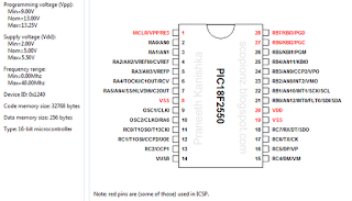
PIC18F2550 Datasheet

18F2550 Pin
pin connection


on line

Labels

Recent comment

Visitors

Free counters!
Copyright © 2012 - Scorpionz™.,All rights reserved | Powered by Blogger