 |
| Speedometer |
How Electronic Speedometers Work
In Electronic speedometer, small magnets attached to the vehicle's rotating drive shaft sweep past tiny magnetic sensors (either reed switches or Hall-effect sensors) positioned nearby. Each time the magnets pass the sensors, they generate a brief pulse of electric current. An electronic circuit counts how quickly the pulses arrive and converts this into a speed, displayed electronically on the display. Since the circuit is measuring the number of wheel rotations, it can also keep a count of how far you have traveled, doubling-up as an odometer (distance-measuring meter). Electronic speedometers can also display speeds with analog pointers and dials, just like traditional eddy-current speedos: in that case, the electronic circuit drives a highly controllable electric motor (called a stepper motor) that rotates the pointer through an appropriate angle. Electronic speedometers are more reliable and compact than mechanical ones and the motion sensors can be any distance from the display that shows you your speed, making them suitable for any kind of vehicle!1. A magnet connected to one of the wheels rotates at high speed.
2. Every time it makes one complete revolution, it passes a magnetic sensor and the field from the magnet triggers the sensor.
3. A circuit translates them into your instantaneous speed and distance traveled.
4. A digital display displaying the speed and distance.
Here I will show you how to build simple yet accurate digital speedometer circuit using just a single IC, seven segments and a few external passive components. The design can be used for all vehicles for indicating their speeds.
 |
| Speedometer Circuit |
The main component of this circuit is PIC16F628A. It count signals receive to RA4, then calculate speed and display it on seven segment. A Reed switch used to sense the speed. If the brightness of seven segments is too much, add 220 – 330 Ohms resistors between PORTB and the display. There are two version of hex files are available. In v1 micro-controller use its internal oscillator and v2 used external 4MHz oscillator.
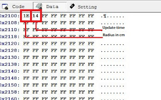
Measure the radius of the wheel and enter it to Eeprom address 0x00. Default value for radius is 30cm (0x1E). You can change update interval by changing the value of Eeprom address 0x01. Default value is 20 (0x14). To increase the sensitivity in this circuit I used two magnets.
 |
| Eeprom Settings |
Maximum Speed is 999 Kmh
Maximum Radius is 255 cm
Supply voltage is 5v
 |
| Circuit Connection |
Posted By :


Please Note: All contents provided on this blog are for non-commercial purposes only.


İyi günler c++ kodu gönderebilirmisiniz ibrahimbas3443@gmail.com
ReplyDelete