Loading...

Sunday, April 19, 2020

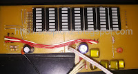
7 Band Real Time Audio Spectrum Analyzer Circuit - 16F819 BA3834S

16F819 Audio Spectrum Analyzer

This is the new version of my previous spectrum analyzer. Used PIC16F819 microcontroller and BA3834 Band-pass filter for spectrum analyzer. It has two versions, BA3834S and BA3834F. Here i used BA3834S. BA3834 are 7-band, band-pass filter ICs that use microprocessor time division to produce serial output for spectrum analyzer displays. To minimize the number of attached components required and enable compact and reliable designs, all of the capacitors for the filters are on the chip. So we can build spectrum analyzer easily

16f819 analizer circuit
Analizer circuit

This circuit included 11 modes (9 patterns, off and random) and it shows which pattern currently running at start-up (S1, S2, etc.). In off mode it shows S0 on display and S+ for random mode. The pattern mode saved to Eeprom to run at next power up. In random mode it changes its pattern in every 3.5 minutes.
PCB, Circuit, and hex available in below

16f819 analizer
16f819 analizer pcb
16f819 analizer pcb


Saturday, February 2, 2019

Uart Controlled DF Player Mikroc Code - 16F628A

  The DFPlayer Mini MP3 Player is a small and low cost MP3 module with an simplified output directly to the speaker. The module can be used as a stand alone module with attached battery, speaker and push buttons or used in combination with a PIC, Arduino or any other with RX/TX capabilities. For this project, I would control the MP3 Player module with a microcontroller and RS232.
DF Player
DF Player

  The DF Player module has all the features which a MP3 player should have. Including advance equalizers, looping and shuffling functions. But here I will show you how to build a simple player with Play/Pause, Next/Preview and vol Up/Down functions. Later you can add more features.

DF Player Pin
DF Player Pin

Specifications:

  • Supported sampling rates (kHz): 8/11.025/12/16/22.05/24/32/44.1/48
  • 24 -bit DAC output, support for dynamic range 90dB , SNR support 85dB
  • Fully supports FAT16 , FAT32 file system, maximum support 32G of the TF card, support 32G of U disk, 64M bytes NORFLASH
  • A variety of control modes, I/O control mode, serial mode, AD button control mode
  • Audio data sorted by folder, supports up to 100 folders, every folder can hold up to 255 songs
  • 30 level adjustable volume
  • 6 -level EQ adjustable
Stand-alone Circuit
Stand-alone Circuit

Circuit:

DF Palyer Circuit
DF Palyer Circuit

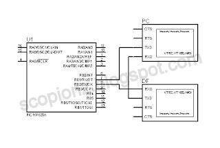
In this circuit I used PIC16F628A and its configure to run using its internal oscillator. For sending commands to the PIC i used uart terminal that built in with Mikroc and u need a TTL converter module fo that. Rx pin of df player connected to the PIC's Tx and Rx pin of PIC connected to the TTL converter's Tx.
Rx pin of TTL converter connected to the df player's Tx (optional)

Uart TTL Module
Uart TTL Module
USB TTL Module
USB TTL Module

Connect circuit as above and plug usb or TF card.Then open uart terminal and enter commands as below..
r - Play, s - Pause, n - Next, p - Previous, u - Vol+, d - Vol-.

df palyer connection
Df palyer connection

Circuit in dot board

Code:

This code was written by using mikroC PRO for PIC v6.

/**************************************************************************

DF Player
Copyright (C) 2019 Scorpionz

This program is free software: you can redistribute it and/or modify
it under the terms of the GNU General Public License as published by
the Free Software Foundation, either version 3 of the License, or
(at your option) any later version.

This program is distributed in the hope that it will be useful,
but WITHOUT ANY WARRANTY; without even the implied warranty of
MERCHANTABILITY or FITNESS FOR A PARTICULAR PURPOSE. See the
GNU General Public License for more details.

You should have received a copy of the GNU General Public License
along with this program.

>> Email: scorpionzblog@gmail.com
>> Blog : scopionz.blogspot.com

***************************************************************************/

char df_rd[10], dump, j, u_data;

void Write_Df_Data(char cmd, char data_H, char data_L) //------- df data ----
{
  char m = 0;
  char df_wr[] = {0x7E,0xFF,0x06,0,0,0,0,0xEF};
       df_wr[3]= cmd;
       df_wr[5]= data_H;
       df_wr[6]= data_L;

   Delay_ms(100);
   for (m=0; m<8; m++) UART1_Write(df_wr[m]);
   Delay_ms(300);
}


void interrupt() {   //-------- interrupt --------------------------------------

 if (PIR1.RCIF) {    //------- Usart interrupt ----------
      PIE1.RCIE = 0;
      u_data = UART1_Read();

    if(u_data==0x7E)  {    // check first byte 0x7E
      for (j=1; j<10; j++) { // read next 9 bytes 0xFF, 0x06, 0x03, 0x00, 0x00, 0x01, 0xFE, 0xF7, 0xEF
No:
        if(UART1_Data_Ready()) {    // Check, is data Ready..?
           df_rd[j] = UART1_Read();
           }
          else goto No;
        }
       
        delay_ms(50);
        if(UART1_Data_Ready()) dump = UART1_Read(); //remove duplicate data
      
        if(df_rd[9]==0xEF) { //check last byte 0xEF
         delay_ms(100);
         if(df_rd[3]==0x3C) Write_Df_Data(0x01,0,0); //play next song
         for (j=0; j<10; j++) df_rd[j]=0;            //clear read buffer
        }
      }
     
     else { //------ keyboard commands -------------
            if(u_data=='n') Write_Df_Data(0x01,0,0); //next
            if(u_data=='p') Write_Df_Data(0x02,0,0); //prev
            if(u_data=='u') Write_Df_Data(0x04,0,0); //vol+
            if(u_data=='d') Write_Df_Data(0x05,0,0); //vol-
            if(u_data=='r') Write_Df_Data(0x0D,0,0); //resume
            if(u_data=='s') Write_Df_Data(0x0E,0,0); //stop
           }
    PIE1.RCIE =1;
    PIR1.RCIF =0;
  }
}


void main()
{
 PCON.OSCF = 1;   //4MHz Internal OSC
 CMCON  |= 0x07;  //Disable Comparators

 INTCON.GIE=1;
 INTCON.PEIE=1;
 PIE1.RCIE=1;

 TRISA = 0x00;
 TRISB = 0xFE;  //Tx Rx
 PORTA = 0;
 PORTB = 0;

 Delay_Ms(3000);   // Df initialization 1.5 ~ 3Sec
 UART1_Init(9600);
}


Wednesday, January 2, 2019

Rotary Encoder Decoder Circuit - PIC12F683 Microcontroller

   Recently I need a rotary encoder circuit for my amplifier. So I searched the internet and test some circuits and codings I found. But nothing work for me. Some are worked but not accurate. So i decided to build my own.

What Is Rotary Encoder

Typical Rotary Encoder
   A rotary encoder is a special type of switch that converts the motion of the switch (clockwise or counterclockwise) into an output signal that can be used to determine what direction the knob is being rotated. There are many different types of rotary encoders which use different technologies and construction materials, however, today we’ll be looking specifically at quadrature rotary encoders which are the most common for general electronics. They're used in many applications such as the manual volume control or tuning on a car stereo.

   A quadrature rotary encoder is similar to a potentiometer, however, a rotary encoder doesn’t have limiting points in the rotation; it will rotate infinitely in either direction. Quadrature rotary encoders don’t output an absolute, fixed position, but rather have a number of increments per 360 degrees, and each increment consists of digital pulses known as ‘grey code’. Most encoders have detents which give tactile feedback every time they increment, however, you can also get smooth encoders without detents, usually with a higher number of steps per rotation.

How do They Work?

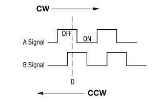
Quadrature Output Table
   It has three pins: A, C, and B. C is the common ground for A and B. A and B are the signal pins. When you rotate the knob, A and B come into contact with the common ground pin, in a particular order depending on the direction you are rotating the knob. When each pin comes into contact with the common ground, they produce a signal. These signals are shifted out of phase with each other as one pin connects before the other pin. This is called quadrature encoding. You need to listen to those pins and the way they pulse in order to determine the direction and number of steps.

The Circuit

   In my circuit I used PIC12F683 microcontroller. It configured to run using its internal oscillater at 8Mhz and internal pull up enable for GP1. And used few components. 0.47uf capacitor used to avoid noices making by rotary encoder. GP0 indicate rotation and GP4 and 5 indicate direction.

Rotary Encoder Circuit

The Coding

   The code was written by using Mikroc Pro for pic.

/**************************************************************************

Rotary Encoder
Copyright (C) 2019 Scorpionz

This program is free software: you can redistribute it and/or modify
it under the terms of the GNU General Public License as published by
the Free Software Foundation, either version 3 of the License, or
(at your option) any later version.

This program is distributed in the hope that it will be useful,
but WITHOUT ANY WARRANTY; without even the implied warranty of
MERCHANTABILITY or FITNESS FOR A PARTICULAR PURPOSE. See the
GNU General Public License for more details.

You should have received a copy of the GNU General Public License
along with this program.

>> Email: scorpionzblog@gmail.com
>> Blog : scopionz.blogspot.com

***************************************************************************/

#define SW       GPIO.F1

void Interrupt()
{

INTCON.GIE = 0;   //Disable Global Interupt
  if(INTCON.INTF)  //RB0/INT External Interrupt Flag bit is set
    {
     if(SW) GPIO.F4=1;
     else   GPIO.F5=1;
     GPIO.F0=1;
     delay_ms(100);
     GPIO   = 0;
    }
INTCON.INTF = 0; //Clear RB0/INT External Interrupt Flag bit
INTCON.GIE = 1;  //Enable Global Interrupt
}

void main()
{
OSCCON = 0x75;
ADCON0 = 0x00;
CMCON0 = 0x07; // Disable Comparators
CMCON1 = 0x00;
ANSEL  = 0x00;

INTCON.GIE = 1; // Global Interrupt Enable
INTCON.INTE = 1; // RB0/INT External Interrupt Enable bit
OPTION_REG = 0b00111111; // wpu & int fall

TRISIO = 0b00000110;
WPU = 0b00000010;
GPIO   = 0b00000001;
delay_ms(500);
GPIO   = 0;
}

Saturday, November 4, 2017

DS3231 RTC Clock mikro C Demo Code - 16F648A


LCD Clock
LCD Clock

Introduction:

The DS323x is a low-cost, extremely accurate I²C real-time clock (RTC) with an integrated temperature-compensated crystal oscillator (TCXO) and crystal. The device incorporates a battery input, and maintains accurate timekeeping when main power to the device is interrupted. The integration of the crystal resonator enhances the long-term accuracy of the device as well as reduces the piece-part count in a manufacturing line. The DS323x is available in commercial and industrial temperature ranges, and is offered in a 16-pin, 300-mil SO package.

DS3231 Block Diagram
The RTC maintains seconds, minutes, hours, day, date, month, and year information. The date at the end of the month is automatically adjusted for months with fewer than 31 days, including corrections for leap year. The clock operates in either the 24-hour or 12-hour format with an active-low AM/PM indicator. Two programmable time-of-day alarms and a programmable square-wave output are provided. Address and data are transferred serially through an I²C bidirectional bus.

Most RTCs use an external 32kHz timing crystal that is used to keep time with low current draw. And that’s all well and good, but those crystals have slight drift, particularly when the temperature changes (the temperature changes the oscillation frequency very very very slightly but it does add up!) This RTC is in a beefy package because the crystal is inside the chip! And right next to the integrated crystal is a temperature sensor. That sensor compensates for the frequency changes by adding or removing clock ticks so that the timekeeping stays on schedule.

DS3231 module
DS3231 module

This is the finest RTC you can get, and now it in a compact, breadboard-friendly breakout. With a coin cell plugged into the back, you can get years of precision timekeeping, even when main power is lost. Great for data-logging and clocks, or anything where you need to really know the time.

The Circuit:

The circuit is very simple. It used PIC16F648A Pic micro, 16x2 LCD and DS3231 RTC module. The PIC used it's internal oscillator and run at 4MHz. Proteus and Hex file can download from the bottom of the page.

DS323x RTC Clock Circuit


MikroC PRO Source Code:

/**************************************************************************

DS323x RTC Clock Demo
Copyright (C) 2017 Scorpionz

This program is free software: you can redistribute it and/or modify
it under the terms of the GNU General Public License as published by
the Free Software Foundation, either version 3 of the License, or
(at your option) any later version.

This program is distributed in the hope that it will be useful,
but WITHOUT ANY WARRANTY; without even the implied warranty of
MERCHANTABILITY or FITNESS FOR A PARTICULAR PURPOSE. See the
GNU General Public License for more details.

You should have received a copy of the GNU General Public License
along with this program.

>> Email: scorpionzblog@gmail.com
>> Blog : scopionz.blogspot.com

***************************************************************************/


// Software I2C connections
sbit Soft_I2C_Scl at RB2_bit;
sbit Soft_I2C_Sda at RB1_bit;
sbit Soft_I2C_Scl_Direction at TRISB2_bit;
sbit Soft_I2C_Sda_Direction at TRISB1_bit;
// End Software I2C connections

// LCD module connections
sbit LCD_RS at RB0_bit;
sbit LCD_EN at RB3_bit;
sbit LCD_D4 at RB4_bit;
sbit LCD_D5 at RB5_bit;
sbit LCD_D6 at RB6_bit;
sbit LCD_D7 at RB7_bit;

sbit LCD_RS_Direction at TRISB0_bit;
sbit LCD_EN_Direction at TRISB3_bit;
sbit LCD_D4_Direction at TRISB4_bit;
sbit LCD_D5_Direction at TRISB5_bit;
sbit LCD_D6_Direction at TRISB6_bit;
sbit LCD_D7_Direction at TRISB7_bit;
// End LCD module connections

char seconds, minutes, hours, day, date, month, year, tem_l, tem_h; // Global variables

//--------------------- Reads time and date information from RTC (DS3231)
void Read_Time()
{
Soft_I2C_Start(); // Issue start signal
Soft_I2C_Write(0xD0); // Address DS3231, see DS3231 datasheet
Soft_I2C_Write(0); // Start from address 0
Soft_I2C_Start(); // Issue repeated start signal
Soft_I2C_Write(0xD1); // Address DS3231 for reading R/W=1

seconds = Bcd2Dec(Soft_I2C_Read(1)); // Read seconds byte
minutes = Bcd2Dec(Soft_I2C_Read(1)); // Read minutes byte
hours = Bcd2Dec(Soft_I2C_Read(1)); // Read hours byte
day = Bcd2Dec(Soft_I2C_Read(1)); // Read day byte
date = Bcd2Dec(Soft_I2C_Read(1)); // Read date byte
month = Bcd2Dec(Soft_I2C_Read(1)); // Read month byte
year = Bcd2Dec(Soft_I2C_Read(1)); // Read year byte

Bcd2Dec(Soft_I2C_Read(1)); // Alarm
Bcd2Dec(Soft_I2C_Read(1));

Bcd2Dec(Soft_I2C_Read(1)); // Data
Bcd2Dec(Soft_I2C_Read(1));

Bcd2Dec(Soft_I2C_Read(1));

tem_h = Bcd2Dec(Soft_I2C_Read(1)); // Temp
tem_l = Bcd2Dec(Soft_I2C_Read(0));

Soft_I2C_Stop(); // Issue stop signal
}

void write_data(char address, char w_data)
{
Soft_I2C_Start(); // issue I2C start signal
Soft_I2C_Write(0xD0); // send byte via I2C (device address + W)
Soft_I2C_Write(address); // send byte (address of DS3231 location)
Soft_I2C_Write(w_data); // send data (data to be written)
Soft_I2C_Stop(); // issue I2C stop signal
delay_ms(50);
}

//-------------------- Output values to LCD
void Display_Time()
{
Lcd_Chr(2, 7, (hours / 10) + 48);
Lcd_Chr(2, 8, (hours % 10) + 48);
Lcd_Chr(2,10, (minutes / 10) + 48);
Lcd_Chr(2,11, (minutes % 10) + 48);
Lcd_Chr(2,13, (seconds / 10) + 48);
Lcd_Chr(2,14, (seconds % 10) + 48);

Lcd_Chr(2,16, (day % 10) + 48); // day
}

void Display_Date()
{
Lcd_Out(1,1,"Date: "); // Prepare and output static text on LCD
Lcd_Chr(1,9,'-');
Lcd_Chr(1,12,'-');
Lcd_Out(1,13,"20"); // start from year 2000

Lcd_Chr(1, 7, (date / 10) + 48);
Lcd_Chr(1, 8, (date % 10) + 48);
Lcd_Chr(1,10, (month / 10) + 48);
Lcd_Chr(1,11, (month % 10) + 48);
Lcd_Chr(1,15, (year / 10) + 48);
Lcd_Chr(1,16, (year % 10) + 48);
}
void Display_Temp()
{
Lcd_Out(1, 1,"Temp: +");
Lcd_Out(1,13,"ßC ");
Lcd_Chr(1,10,'.');

tem_l=tem_l*25;

Lcd_Chr(1, 8, ((tem_h & 127) / 10) + 48);
Lcd_Chr(1, 9, ((tem_h & 127) % 10) + 48);
Lcd_Chr(1, 11, (tem_l / 10) + 48);
Lcd_Chr(1, 12, (tem_l % 10) + 48);

if(tem_h & 128) Lcd_Chr(1, 7, '-');
}

//------------------ Performs project
void Init_Main()
{
PCON.OSCF = 1; //4MHz
CMCON |= 0x07; // Disable Comparators CMCON |= 7;
OPTION_REG = 0;

Soft_I2C_Init(); // Initialize Soft I2C communication
Lcd_Init(); // Initialize LCD
Lcd_Cmd(_LCD_CLEAR); // Clear LCD display
Lcd_Cmd(_LCD_CURSOR_OFF); // Turn cursor off

Lcd_Out(1,3,".:Scorpionz:.");
Delay_ms(500);
Lcd_Out(2,1,"Ds3231 RTC Clock");
Delay_ms(1500);
Lcd_Cmd(_LCD_CLEAR);
Lcd_Out(2,1,"Time: ");
Lcd_Chr(2,9,':');
Lcd_Chr(2,12,':');

write_data(14,0x40); //SQWE output at 1 Hz
}

//----------------- Main procedure
void main() {
Delay_ms(500);

Init_Main(); // Perform initialization

while (1) { // Endless loop
Read_Time(); // Read time from RTC(DS3231)
Display_Time(); // Prepare and display on LCD
Display_Date(); Delay_ms(450);
Display_Temp();
Delay_ms(450);
}
}

Saturday, December 26, 2015

Multi Stage Simple Programmable Timer Circuit - 16F628A

255 Stages Simple Programmable Timer Circuit

Electronic delay timers are devices which are able to count and produce different time delay intervals as per the external settings. The elapsing of the set time is mostly indicated through an audible alarm to alert the user. Timers play an important role in our everyday life, whether it’s your cell phone, wall clock, TV/DVD sets, computers they are present everywhere.

Usually an ordinary electronic timer is able to produce single-shot delay intervals and setting up its initializing point becomes inaccessible. The present simple programmable timer circuit design eliminates this drawback.

Simple Programmable Timer Circuit - 16F628
Simple Programmable Timer Circuit

This is a one of the simple circuit of programmable timer circuit. The time range of this timer is 1 second to 255 hours. The delay time can be change by dip switches. The whole circuit of programmable timer is build using cheap PIC16F628A microcontroller and few passive components.

Circuit Operation

After power applied, the START led will turn on and you need to configure the delay time, timer mode and repeat mode. The delay time of this circuit can change by using dip switches. Those dip switches are represent 8-bit binary number and that number use to set delay time. When the delay time over, RLY ON led will turn on.

Eg:
If you need to set delay time to 150 then, dip switch configuration is 10010110 (RB0-RB7).
1 = Off and 0 = On

When you pressed the START button, START led will begin to blink and you can observe timer status by that.

Time Mode

This circuit can operate in 3 different time modes (Seconds, Minutes and Hours). Those modes can select from MODE buttons.

  1. If both PORTA.F6 and PORTA.F7 are low or high, then circuit is running in seconds’ mode (0 – 255 seconds)
  2. If PORTA.F6 high and PORTA.F7 low, then the circuit is running in minutes’ mode (0 – 255 minutes)
  3. If PORTA.F6 low and PORTA.F7 high, then the circuit is running in hours’ mode (0 – 255 hour)

Repeat Mode

If PORTA.F1 is low then repeat mode will turn on. The circuit running continuously and RLY ON led will turn on and off repeatedly.

To control heavy load, remove RLY ON led and connect 5v relay through NPN transistor. Then connect you device across the relay. Supply voltage for this circuit is 5v and use voltage regulator ic such as LM7805, if you use voltage above that.


on line

Labels

Recent comment

Visitors

Free counters!
Copyright © 2012 - Scorpionz™.,All rights reserved | Powered by Blogger