Saturday, December 26, 2015

Multi Stage Simple Programmable Timer Circuit - 16F628A

255 Stages Simple Programmable Timer Circuit

Electronic delay timers are devices which are able to count and produce different time delay intervals as per the external settings. The elapsing of the set time is mostly indicated through an audible alarm to alert the user. Timers play an important role in our everyday life, whether it’s your cell phone, wall clock, TV/DVD sets, computers they are present everywhere.

Usually an ordinary electronic timer is able to produce single-shot delay intervals and setting up its initializing point becomes inaccessible. The present simple programmable timer circuit design eliminates this drawback.

Simple Programmable Timer Circuit - 16F628
Simple Programmable Timer Circuit

This is a one of the simple circuit of programmable timer circuit. The time range of this timer is 1 second to 255 hours. The delay time can be change by dip switches. The whole circuit of programmable timer is build using cheap PIC16F628A microcontroller and few passive components.

Circuit Operation

After power applied, the START led will turn on and you need to configure the delay time, timer mode and repeat mode. The delay time of this circuit can change by using dip switches. Those dip switches are represent 8-bit binary number and that number use to set delay time. When the delay time over, RLY ON led will turn on.

Eg:
If you need to set delay time to 150 then, dip switch configuration is 10010110 (RB0-RB7).
1 = Off and 0 = On

When you pressed the START button, START led will begin to blink and you can observe timer status by that.

Time Mode

This circuit can operate in 3 different time modes (Seconds, Minutes and Hours). Those modes can select from MODE buttons.

  1. If both PORTA.F6 and PORTA.F7 are low or high, then circuit is running in seconds’ mode (0 – 255 seconds)
  2. If PORTA.F6 high and PORTA.F7 low, then the circuit is running in minutes’ mode (0 – 255 minutes)
  3. If PORTA.F6 low and PORTA.F7 high, then the circuit is running in hours’ mode (0 – 255 hour)

Repeat Mode

If PORTA.F1 is low then repeat mode will turn on. The circuit running continuously and RLY ON led will turn on and off repeatedly.

To control heavy load, remove RLY ON led and connect 5v relay through NPN transistor. Then connect you device across the relay. Supply voltage for this circuit is 5v and use voltage regulator ic such as LM7805, if you use voltage above that.

Thursday, November 26, 2015

Simple and Accurate LC Meter Circuit - 16F690

Simple and Accurate LC Meter - 16F690
Digital LC Meter

A LCR meter [Inductance (L), Capacitance (C), and Resistance (R)] is a piece of electronic test equipment used to measure the inductance, capacitance and, resistance of a component. Inductance is the property of an electrical circuit causing voltage to be generated proportional to the rate of change in current in a circuit. In Electronics, capacitance is the ability of a body to hold an electrical charge. Capacitance is also a measure of the amount of electrical energy stored (or separated) for a given electric potential. The electrical resistance of an electrical element measures its opposition to the passage of an electric current. The meter reads L, C and R directly with no human calculation required.

Recently I found this LC meter project on internet and I was looking for that kind of project. Therefore, I build. Amazing it is work! Also the accuracy of this LC meter is great and it is very easy to build. So that, I post it here, because I think it is useful to you. You can visit original post from using this link: LMC3

The data below were determined based on theoretical calculations, the scale and the display automatically change.

Min Max Resolution Accuracy
Non Polar Condenser 1pF 1nF 0.1pF 1%

1nF 100nF 1pF  1%

100nF 1uF  1nF 2.5%
Electrolytic Capacitor 100nF 100,000uF 1nF 5%
Inductor 10nH 20H 10nH 5%
Resistance 1mΩ 0.5Ω 1mΩ 5% 
Inductance 0.5Ω 30Ω 10mΩ 10%
Specifications of the LC Meter


Simple and Accurate LC Meter Circuit
LC Meter Diagram


LC Switch:
The purpose of this is, switch between inductance and capacitance mode. When you turn on the LC meter, you should set it to C mode.

Calibration Switch:
You can calibrate LC meter by pressing this. See Calibration for more details.

LC Meter Calibration

You have 3 modes to calibrate. When the process is completed, calibrated values are saving to the microcontroller’s internal EEPROM, so of course they are available after the re-start.

C Calibration
  1. Switch on
  2. Switch L/C switch to C position
  3. Leave the test probes freely. Do not even touch it
  4. Press and hold the CALIB button until the message Switch to meas. Then release the button
  5. Wait for the appearance of 0.00 pF
L Calibration
  1. Switch on
  2. Switch to the L position
  3. Connect L/C probe and GND probe together
  4. Press and hold the CALIB button until the message Switch to meas. Then release the button
  5. Wait for the appearance of 0.00 uH
ESR Calibration
  1. Switch on
  2. Switch to the C position
  3. Connect LE probe and GND probe together
  4. Press and hold the CALIB button until the message Switch to meas. Then release the button
  5. Note the value shown on the screen
Calibration Values
  • F0 = 499.9k
  • Fcal = 355.9k
  • Re = 180Ω
  • Uesr0 = 58.3mV
  • Fesr = 83.6k
  • Rx = 0mΩ [-5mΩ to 5mΩ]

Critical Components

All the below resistors are 1%.
(In my circuit, I used normal resistors and those are measured using digital multimeter)

  • 47Ω - R11
  • 47kΩ - R8
  • 100kΩ - R3-R5
  • 1nF - C8, C11 (Polypropylene or Polyester)
  • 33nF - C10 (Polypropylene 275V AC)
  • 10uF - C7, C9 (Tantalum)
  • 100uH - L1 (Low-loss DC resistance of 0.3-0.4Ω)

Testing


Simple and Accurate LC Meter Circuit - 16F690 test c
check 22pF ceramic capacitor

Simple and Accurate LC Meter Circuit - 16F690 test e
check 100uF electrolytic capacitor

Simple and Accurate LC Meter Circuit - 16F690 test l
check 100uH inductor

I was unable to find a reed relay, so I put 5v ordinary relay temporarily. In addition, my PCB designed for the TL2285 switches. But, I bought TL2230 by mistake :)

If the back-light brightness is low, you can increase back-light brightness by decreasing the value of the resistor R2 to 470Ω - 1k. You can change display contrast by adjusting 10k preset.
For PCB, Schematic and hex file, click download button.

You need to discharge capacitors properly before measuring.

Monday, November 23, 2015

MikroC Programming Guide

PIC Microcontrollers - Programming in C
Microcontroller Programmer

The purpose of this post is to provide basic information that one needs to know in order to be able to use microcontrollers successfully in practice. This post, therefore, doesn’t contain any super interesting program or device schematic with amazing solutions. Instead, the following examples are better proof that program writing is neither a privilege nor a talent issue, but the ability of simply putting puzzle pieces together using directives. Rest assured that design and development of devices mainly consists of the ‘test-correct-repeat’ work. Of course, the more you are in it, the more complicated it gets since the puzzle pieces are put together by both children and first-class architects.

Copyright © 1998–2012. MikroElektronika. All rights reserved. All trade and/or services marks mentioned are the property of their respective owners.

4.0 TABLE OF CONTENTS

Wednesday, November 18, 2015

Programmable Digital Seven Segment Timer Circuit - 16F628

Programmable Digital Timer Circuit
Seven Segment Timer


A timer is a specialized type of clock for measuring time intervals. By function, timers can be categorized to two main types. Those are Counts upwards and counts downward.

Timers originally designed to fulfill a need in industry for a means of keeping time on certain devices. Originally, these timers were mechanical devices and used clockwork mechanisms as a means of keeping a regular time. The invention of two electromechanical timer designs allowed for more precise time measurement. The first uses the principle of heat expansion to increase the temperature of a metal finger made of two different metals with differing rates of thermal expansion. As electric current flows through the metal, it begins to heat and one side expands more quickly than the other does, which in turn, moves the electrical contact away from an electrical switch contact. The second uses a small AC motor, which turns at a predetermined rate due to the application of an alternating current.

Finally, digital timers invented. Digital logic circuits are now so cheap that it has become a better investment to buy a digital timer than a mechanical or electromechanical timer. Individual timers implemented with single chip circuits.

This is a very simple adjustable digital timer circuit based on the PIC16F628A microcontroller and it can be programmed to schedule the on and off operation of an electrical appliance. This timer consists of three parts: power supply, control circuit and display. Working voltage of the circuit is 5v - 12v. It depends on the relay voltage. If you use 5v relay then you can omitted the LM7805 regulator IC and apply 5v directly. Otherwise, you have to use regulator IC and apply suitable voltage according to the relay voltage. The schematic is very simple and accurate of the circuit is very good. PIC use its internal oscillator.

Programmable Digital SSD Timer Circuit - PIC16F628A
Programmable Digital Timer Schematic


There are two versions of hex file are available. Those are "4dg_tmr_min.hex" and "4dg_tmr_hr.hex". The first file for the minute timer. It display minutes and seconds. Adjustable time is 1 second to 60 minutes. Other hex file for hourly timer and its adjustable time is 1 minute to 24 hours. This will display hours and minutes on the seven segments.

Configuration

If the time runs too fast or too slow, you can able to adjust the speed by changing the value of Eeprom address 0. Default value is 44 (0x2c). Typical value is 59 (0x3B). Maximum is 255 (0xFF). In repeat mode delay time before restart the timer, determine by value of Eeprom address 3. Default value is 10 (0x0A). Maximum is 255 (0xFF). See below picture for more details.

Programmable Digital Timer Circuit configuration
Eeprom Configuration

Operation of the timer

This circuit uses 5 push buttons to control the their functions.
  • START/PAUSE: When the timer is on, the device is in pause condition even the switch was in closed position. Pressing this button, you can switch between the start and pause timer.
  • FOR/BACKWARD: This allows you to select counter mode. Either upwards or count down.
  • REPEAT: When the timer reaches 00:00, it starts again from previous value you set.
  • LEFT/RIGHT: This allows you to change values on display. The selected digit is incremented by pressing those buttons and values on the display are stored to the Eeprom.

Now connect device you want to operate, through the relay. Set the desired time using left and right buttons and press start. When the timer reaches 00:00, relay will activate.

Sunday, November 8, 2015

Digital LCD Speedometer and Odometer Circuit - 16F628

speedo odometer
Speedometer


In my previous post, I explained how to build a simple speedometer circuit using a micro-controller and seven segments. Read it from here. This is a further development of that circuit. This circuit indicates both speed and distance.

A speedometer or a speed meter is an instrument that measures and displays the instantaneous speed of a vehicle. An odometer or odograph is an instrument that indicates distance traveled by a vehicle.

speedo odometer circuit
Speedometer + Odometer Circuit


For this circuit I used PIC16F628A micro-controller and 16x2 LCD. You can able to see speed in first line and distance in second line on the LCD. Distance will update every 100 meters and speed updates every one second. Value of distance writes to Eeprom in every 1 km. I also added a button to this circuit. The purpose is, reset the distance to zero.

Same as the Speedometer Circuit, micro-controller count the signals received to RA4 pin and then calculate speed and distance, then display information on LCD. 8 MHz resonator is use to generate clock signals. However, you can always use crystal for it and make sure to add 22pf ceramic capacitors if you use crystal oscillator.

Measure the radius of the wheel and enter it to Eeprom address 0x00. Default value for radius is 30cm (0x1E). I used two magnets to operate reed switch. Please refer my previous post for more details and circuit connection.

Maximum speed is 999 kmh
Maximum distance is 9999 km
Supply voltage is 5v

Friday, November 6, 2015

Digital Seven Segment Speedometer Circuit - 16F628

speedometer1
Speedometer

How Electronic Speedometers Work

In Electronic speedometer, small magnets attached to the vehicle's rotating drive shaft sweep past tiny magnetic sensors (either reed switches or Hall-effect sensors) positioned nearby. Each time the magnets pass the sensors, they generate a brief pulse of electric current. An electronic circuit counts how quickly the pulses arrive and converts this into a speed, displayed electronically on the display. Since the circuit is measuring the number of wheel rotations, it can also keep a count of how far you have traveled, doubling-up as an odometer (distance-measuring meter). Electronic speedometers can also display speeds with analog pointers and dials, just like traditional eddy-current speedos: in that case, the electronic circuit drives a highly controllable electric motor (called a stepper motor) that rotates the pointer through an appropriate angle. Electronic speedometers are more reliable and compact than mechanical ones and the motion sensors can be any distance from the display that shows you your speed, making them suitable for any kind of vehicle!


electronic speedometer
1. A magnet connected to one of the wheels rotates at high speed.

2. Every time it makes one complete revolution, it passes a magnetic sensor and the field from the magnet triggers the sensor.

3. A circuit translates them into your instantaneous speed and distance traveled.

4. A digital display displaying the speed and distance.


Here I will show you how to build simple yet accurate digital speedometer circuit using just a single IC, seven segments and a few external passive components. The design can be used for all vehicles for indicating their speeds.

ssd speedometer circuit
Speedometer Circuit

The main component of this circuit is PIC16F628A. It count signals receive to RA4, then calculate speed and display it on seven segment. A Reed switch used to sense the speed. If the brightness of seven segments is too much, add 220 – 330 Ohms resistors between PORTB and the display. There are two version of hex files are available. In v1 micro-controller use its internal oscillator and v2 used external 4MHz oscillator.

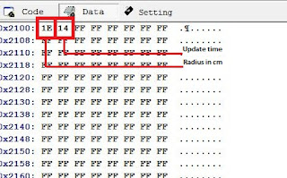
Measure the radius of the wheel and enter it to Eeprom address 0x00. Default value for radius is 30cm (0x1E). You can change update interval by changing the value of Eeprom address 0x01. Default value is 20 (0x14). To increase the sensitivity in this circuit I used two magnets.


speedometer eeprom settings
Eeprom Settings


Maximum Speed is 999 Kmh
Maximum Radius is 255 cm
Supply voltage is 5v


speedometer connection
Circuit Connection

Thursday, November 5, 2015

Simple LED Light Meter Circuit - LB1403

Light Meter


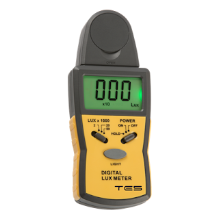
A light meter is a device having a light sensor at one end and a window at the other end which displays the reading that indicates the current light conditions. Light meters are often used in the fields of cinematography, photography and also in test cricket in order to determine the optimum light level for a scene.

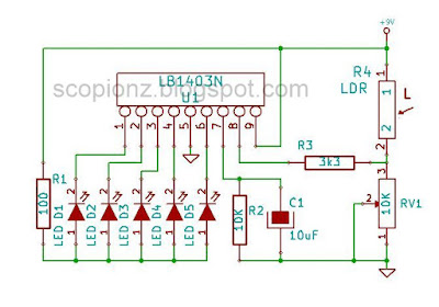
Using LB1403 IC and LDR, we can able to build a cheap light meter. LEDs are used to observe the current light conditions and variable resistor is used for adjust the sensitivity. If the LEDs are too bright, change R1 value (220 - 470 ohms). Supply voltage is 6 - 12V.

Simple LED Light Meter Circuit - LB1403
Light Meter Schematic

Wednesday, November 4, 2015

Simple Automatic Brightness Control Circuit

Automatic Brightness Control

Automatic Brightness Control is the automatic adjustment of the exposure factors such as mA and V. ABC is used to keep the brightness of the display or bulb at a constant level. It involves the adjustment of the V and mA automatically depending on the part of the anatomy being examined. This can be achieved using a LDR, for instance, which monitors the ambient light and change its resistance this resistance changing use to adjust the V, the mA (or both) accordingly.

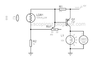
Automatic Brightness Control Circuit

This simple auto brightness adjusting circuit composed with a LDR. The LDR connected with the Base pin of the PNP transistor. By the LDR feature that its resistance changes with the ambient light, the voltage of Base change. When the ambient light is bright, the resistance of LDR is low, and the voltage of Base is reducing and the ambient light is low, the resistance of LDR is high, and the voltage of Base is rising. Then the output voltage of transistor is changing. The variable resistor is use to adjust the sensitivity of circuit. Supply voltage for this circuit is 12v.

Light Dependent Resistors (LDR)


Light Dependent Resistor
A Light Dependent Resistor (LDR) is a resistor that changes in value according to the light falling on it. An LDR commonly has a high resistance in the dark, and a low resistance in the light.

Sunday, September 20, 2015

Simple Power Guard Circuit - 12F683

Update
2015-10-05 Wrong circuit diagram - Fixed

Power Guard
Power Guard

This is a very simple and accurate power guard circuit. This circuit is useful to guard the electronic or electrical devices from mains transients and spikes. Very high spikes can develop at power on due to sparking in the switch and more serious effects occur when power resumes after a power failure due to high magnetic field in the distribution transformer. This will damage your device permanently. To avoid such damages we can use this circuit.

This circuit used cheap PIC12F683 micro-controller. It controls all the functions of power guard. After power is applied, the green LED starts to blink. This circuit gives a time delay before giving power to the device. Default value is 30 seconds. However, you can change this value. See configuration for more details. After this delay, Green LED turns on permanently. Then Relay activates and connects power to the device.

When the power is abnormal Yellow or Red LED turns on and relay will turn off to protect our device. The Green LED will start to flash again and after delay time it check power status and turn relay on if the voltage is good. Yellow LED indicates low voltage and Red LED indicate high voltage. If all the LEDs are turn on, that indicates firmware error and pleases re-programmed micro-controller.

Simple Power Guard Circuit Diagram
Circuit Diagram v2

Configuration and Calibration 

For this circuit I used 12v step down transformer. Its output use to sense the power condition. Before using, you need to calibrate this circuit for working correctly. In my project, I choose 240v as normal, 260v as high and 200v as low voltage.

Connect multimeter to GP0 and check voltage. if it exceed 5v immediately turn off power and check the component and connections. (Typical value is 3 - 3.5v)

V = [Tp/12] x [(Vdd/1023) x Eeprom val x 4]
Tp = primary voltage

200 = [240/12] x [(5/1023) x Eeprom val x 4]
260 = [240/12] x [(5/1023) x Eeprom val x 4]

Eeprom value for low condition (200v) = 511 (1FF hex)
GP0 voltage = (2v4)

Eeprom value for high condition (260v) = 664 (298 hex)
GP0 voltage = (3v3)

Write those values to Eeprom.
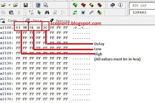
V high = Eeprom (0)*256 + Eeprom (1) - (0x02 and 0x98)
V low = Eeprom (2)*256 + Eeprom (3) - (0x01 and 0xFF)

Simple Power Guard Eeprom settings
Eeprom settings

To change  delay time simply changes the value of Eeprom address 4 (Default 0x3C)

Delay time in seconds = value of Eeprom address / 2
0 < value of Eeprom address < 255 (0 < Delay time in seconds < 127)
Minimum delay time is 0 seconds and maximum delay time is 2 minutes.

Not for the commercial purpose.

/*************************************************************************** Simple Power Guard Copyright (C) 2014 Praneeth Kanishka This program is free software: you can redistribute it and/or modify it under the terms of the GNU General Public License as published by the Free Software Foundation, either version 3 of the License, or (at your option) any later version. This program is distributed in the hope that it will be useful, but WITHOUT ANY WARRANTY; without even the implied warranty of MERCHANTABILITY or FITNESS FOR A PARTICULAR PURPOSE. See the GNU General Public License for more details. You should have received a copy of the GNU General Public License along with this program. If not, see http://www.gnu.org/licenses >> Email: scorpionzblog@gmail.com >> Web : http://scopionz.blogspot.com ***************************************************************************/ #define L_H GPIO.F1 #define L_L GPIO.F2 #define L_K GPIO.F4 #define RLY GPIO.F5 char idx, del=1, v_d, error; int sense, v_h, v_l; void main() { OSCCON = 0x70; // 8Mhz ADCON0 = 0x00; CMCON0 = 0x07; // Disable Comparators CMCON1 = 0x00; ANSEL = 0x01; TRISIO = 0b00000001; OPTION_REG = 0; WPU=0; Delay_ms(10); GPIO = 0; v_h = Eeprom_Read(1) + Eeprom_Read(0)*256; v_l = Eeprom_Read(3) + Eeprom_Read(2)*256; v_d = Eeprom_Read(4); error = Eeprom_Read(5); if(error>101) error=0; Eeprom_Write(5, error+1); Delay_ms(10); //v_h = 664; //v_l = 511; //v_d = 10; //error = 100; while(1) { if(error>99) { RLY=0; L_K=1; L_H=1; L_L=1; while(1); } if(del) { for(idx=0; idx<v_d; idx++) { //60 = 30sec L_K=~L_K; Delay_ms(500); } del=0; } sense=Adc_Read(0); if(sense>v_h) {RLY=0; L_K=0; L_H=1; del=1;} else if(sense<v_l) {RLY=0; L_K=0; L_L=1; del=1;} else {RLY=1; L_K=1; L_H=0; L_L=0;} Delay_ms(500); } }

Monday, June 15, 2015

I2C FM Receiver Circuit with LCD - 16F88 BK1080

Digital FM Receiver
Digital FM Receiver


This is a simple stereo FM radio receiver circuit that can scan with 87.5 MHz and 108 MHz seamlessly between 100 kHz step and it use BK1080 as a receiver IC.

Main components of this receiver are a PIC16F88 micro-controller, 16x2 LCD and BK1080 FM receiver chip. This system is design to work with 5V DC power supply. User interface of this system consist with 6 push buttons and a 16×2 character LCD module. All the functions of this receiver can control by this buttons and necessary information displayed on the LCD.

Specifications of this receiver

  • Easy to build
  • Standby mode
  • Automatic gain control
  • Automatic frequency control
  • Automatic noise suppression
  • Preset memory stations up to 250 (default 20)

Schematic of BK1080 I2C FM Receiver
Schematic of BK1080

BK1080

The BK1080 FM receiver employs a low-IF architecture, mixed signal image rejection and all digital demodulation technology. The stations scan of BK1080 searches radio stations based on both the channel RSSI estimation and signal quality assessment, increases the number of receivable stations while avoids false stops. BK1080 enables FM radio reception with low power, small board space and minimum number of external components. All functions controlled through an I2C serial interface. See datasheet for more details.

Numbers of memory locations are determine by the value of Eeprom 1 (default value 0x14).
You can connect an earphone directly with BK1080’s output. However, do not connect speakers directly with IC. I recommended you to use amplifier if you wish to get more sound. In addition, be carefully when soldering BK1080. Because this IC more sensitive to electrostatic. Use DC soldering Iron to solder this IC or unplug your iron when solder. Micro-controller runs using its internal oscillator. RA0 and RA1 are configuring as SCL and SDA. RA2 is not connected. RA6 pin can directly connect with background light of LCD display. As well as it is also can used for the controlling another device like mute pin of power amp.

Selecting the station:
When we are in the power on mode, on the screen we can see "Frq:107.5 Ch:12" - tuned frequency of the station and then the number of the cell where the recorded frequency of the station. Pressing ‘CH_UP’ and ‘CH_DN’ we can move the recorded stations. Pressing ‘FR_UP’ and ‘FR_DN’ we can change the frequency. ‘STORE’ stored the current frequency to the current station and ‘PWR’ used to toggle standby mode and power on mode

Firmware of this system was written by using MikroC for PIC and schematic, hex and Proteus files are available for download.

Saturday, June 13, 2015

PLL Synthesized FM Receiver Circuit with LCD - 16F88 LM7001

FM Tuner
FM Tuner

This is high quality stereo digital PLL synthesized FM radio receiver circuit that can scan with 76 MHz and 108 MHz seamlessly between 100 kHz step, although the sensitivity is high.

Main components of this receiver are a PIC16F88 micro-controller, 16x2 LCD, LM7001 PLL Frequency Synthesizer, AN7223 IF Amp, TA7343 MPX and a FM Tuner. This system is design to work with 12V DC power supply and the LM7805 and 7808 regulators used to manage power requirements to the above-mentioned components.

User interface of this system consist with 6 push buttons and a 16×2 character LCD module. All the functions of this receiver can control by this buttons and necessary information displayed on the LCD.

Specifications of this receiver

  • High sensitivity
  • Standby mode
  • Preset memory stations up to 250 (default 20)
  • 3-user selectable frequency ranges (default 87.5-108)

Schematic of PLL and Power circuit

Schematic of micro-controller and user interrface

LM7001

The LM7001 is a PLL frequency synthesizer LSIs for tuners, making it possible to make up high performance AM/FM tuners easily. These LSIs are software compatible with the LM7000, but do not include an IF calculation circuit. The FM VCO circuit includes a high-speed programmable divider that can divide directly seven reference frequencies. Serial input circuit for data input (using the CE, CL, and DATA pins)

Tuner 

Anticipating the objection that these tuners do not find, I assure you that if you do not be lazy and go through the repair shops where repair radio. In addition, you can get this tuner from old audio system and car set. There are 3 types.

Types of tuner
Types of tuner

  1. FM Front End only (you need to build IF Amp, MPX circuit)
  2. FM Front End with IF (you need to build MPX)
  3. FM Front End IF and MPX

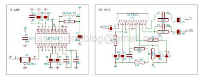
IF Amp and MPX

For IF amp I used AN7223 because it need few external parts and it has high sensitivity and stability. If you cannot find FM quad coil then you can use 2pin 10.7MHZ ceramic resonator for that (see datasheet for more details). However, it is possible to use another IC for this as AN7220, TA7640 and KA2297 etc.

For MPX decoder here I used TA7343. This IC decode mono signal to stereo. This is an optional part. If you wish to work with mono, then omit this part and connect amplifier input with ‘AF’.

IF and MPX circuit
IF and MPX circuit

Complete circuit pcb
Complete circuit

Operation

Numbers of memory locations are determine by the value of Eeprom 1 (default value 0x14) and frequency range is determine by the value of Eeprom 2 (default value 0x00).
  • If value is 1 then range is 76-108MHz
  • If value is 2 then range is 76-90MHz
  • Else, range is 87.5-108 MHz

Selecting the station:
When we are in the power on mode, on the screen we can see "Frq:106.5 Ch:15" - tuned frequency of the station and then the number of the cell where the recorded frequency of the station. Pressing ‘CH_UP’ and ‘CH_DN’ we can move the recorded stations. Pressing ‘FR_UP’ and ‘FR_DN’ we can change the frequency. ‘STORE’ stored the current frequency to the current station and ‘PWR’ used to toggle standby mode and power on mode

Micro-controller runs using its internal oscillator. RA6 pin can directly connect with background light of LCD display. As well as it is also can used for the controlling another device like mute pin of power amp. For VCC (tuning voltage) you can use up-to 12v.

Firmware of this system was written by using MikroC for PIC and schematic, hex and Proteus files are available for download.

Saturday, May 30, 2015

Stereo Bass Booster Circuit with Simple Mixer

Bass Booster
Bass Booster

A Bass Booster is an audio device, which amplifies the low frequencies (bass) within the audio spectrum. This operates in a similar manner to an audio equalizer. General-purpose equalizers are often not effective at boosting very low frequencies, and therefore many electronics enthusiasts make their own circuit to achieve this purpose. Using following circuit you can boost frequencies below 60Hz.

Stereo Bass Booster circuit
Schematic

This circuit is an active circuit and used TL074, which include separate four op-amps. Alternatively, you can use any general-purpose op amp such as LM324, TL084, etc. This circuit is not only a bass booster it also include a simple mixer circuit. U1A and U1D are act as mixer, U1B and U1C for the base boosting. I design this circuit for electronic switching. Therefor I used two transistors for it. To enable bass boost connect ‘ubb’ to positive supply. You can use normal switch for it. In addition, it is possible to enable bass boost by applying voltage signal to ‘ubb’, which come from a micro-controller or any other source. This circuit can operate in either single supply or dual power supply.

For single power supply
  • Omit C20 and C21.
  • Connect positive supply to VDD and Ground (0v) to GND or VAA.
  • Max Supply voltage is 12v.

For dual power supply
  • Remove J3 (jumper), C15, R19 and R20.
  • Add jumper (0 Ohms) for R20 it.
  • Connect positive supply to VDD, negative for VAA and Ground (0v) to GND.
  • Max Supply voltage is +/-12v.

Please ignore the U2, R21, C16, C18 and P1. Those are not necessary for the operation of this circuit. These parts are optional because that this circuit and PCB were designed for my personal project.

Now connect output of this circuit with amplifier input and give your input to the mixer side. This circuit is ideal for high quality sound. If you want that unique clean high-bass sound then this circuit can provide it.

Schematic and PCB files were added to the download and you can download from it below.

Thursday, May 28, 2015

10 Band I2C Graphic Equalizer Circuit - 16F628 TEA6360

Updated:
  • 2016-08-17 - Added small application for calculate frequencies and parts.

10 Band Equalizer
10 Band Equalizer

A graphic equalizer is a high-fidelity audio control that allows the user to see graphically and control individually a number of different frequency bands in a stereophonic system. A typical graphic equalizer consists of several audio filter/amplifiers, each centered at a specific frequency in the audio range. Most graphic equalizers have two identical sets of filter/amplifiers, one for each channel in a stereophonic system.

The gain controls in most graphic equalizers are slide potentiometers that are adjusted by moving a controller up or down. Gain is increased by sliding the upwards. The slide potentiometers for each channel are placed side-by-side, with the lowest-frequency unit at the left and the highest-frequency unit at the right. In this way, the positions of the buttons appear to follow a graphical curve that represents the gain as a function of frequency for each channel.

By using following circuit you can build a 10 band stereo graphic equalizer that can be controlled via I2C system. For this circuit I used two of TEA6360 ICs. Each IC contains two serial five bands equalizer blocks. Therefore, we need two ICs for 10 bands. We can reduce the size of circuit because all the function can be drive via i2C. So that, we do not need connect potentiometers to control the gain of frequency bands like an ordinary equalizer. In addition, we can reduce cost and complexity of circuit using this IC.

10 Band Equalizer circuit
Schematic

10 Band Equalizer pcb
Circuit on PCB

In my demo code, I used 16F628A micro-controller and single button to set equalizer modes. The modes are ‘Flat’, ’Rock‘, ’Pop‘, ’Jazz‘ and ’Party’. The status will indicate by five LEDs those connected to PORTA. In addition, selected mode saved to device Eeprom and load to ICs when start up. However, according to your choice you can able to change the code.

For example if you need to set gain for each frequency manually, then you can add 1 button to each channel and total 10 buttons. For another example, you can add 3 buttons. One button to raise the gain and other to lower and 3rd one for select desired frequency.

The center frequency of each bands are 31Hz, 62Hz, 125Hz, 250Hz, 500Hz, 1KHz, 2KHz, 4KHz, 8KHz and 16KHz. the Q (quality) factor is 1 to 1.2 and PCB, full schematic and sample code can be downloading in below.

Part List

  • C04, 07, 08, 09 = 0.37uF
  • C10, 11, 12, 13 = 0.18uF
  • C14, 15, 16, 17 = 0.01uF
  • C18, 19, 20, 21 = 0.047uF
  • C22, 23, 24, 25 = 0.022uF
  • C27, 28, 30, 31 = 0.01uF
  • C32, 33, 34, 35 = 0.0052uF
  • C36, 37, 38, 39 = 0.0027uF
  • C40, 41, 42, 43 = 0.0015uF
  • C44, 45, 46, 47 = 720pF

TEA6360

The 5-band stereo equalizer is a 12C-bus controlled tone processor for application in car radio sets, TV sets and music centers. It offers the possibility of sound control as well as equalization of sound pressure behavior of different rooms or loudspeakers, especially in cars.

FEATURES
  • Monolithic integrated 5-band stereo equalizer circuit
  • Five filters for each channel
  • Center frequency, bandwidth and maximum boost/cut defined by external components
  • Choice for variable or constant Q-factor via I2C software
  • Defeat mode
  • All stages are DC-coupled
  • I2C-bus control for all functions
  • Two different module addresses programmable.


on line

Labels

Recent comment

Visitors

Free counters!
Copyright © 2012 - Scorpionz™.,All rights reserved | Powered by Blogger