The DFPlayer Mini MP3 Player is a small and low cost MP3 module with an simplified output directly to the speaker. The module can be used as a stand alone module with attached battery, speaker and push buttons or used in combination with a PIC, Arduino or any other with RX/TX capabilities. For this project, I would control the MP3 Player module with a microcontroller and RS232.
The DF Player module has all the features which a MP3 player should have. Including advance equalizers, looping and shuffling functions. But here I will show you how to build a simple player with Play/Pause, Next/Preview and vol Up/Down functions. Later you can add more features.
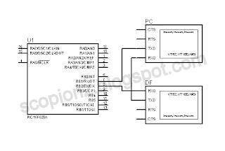
In this circuit I used PIC16F628A and its configure to run using its internal oscillator. For sending commands to the PIC i used uart terminal that built in with Mikroc and u need a TTL converter module fo that. Rx pin of df player connected to the PIC's Tx and Rx pin of PIC connected to the TTL converter's Tx.
Rx pin of TTL converter connected to the df player's Tx (optional)
Connect circuit as above and plug usb or TF card.Then open uart terminal and enter commands as below..
r - Play, s - Pause, n - Next, p - Previous, u - Vol+, d - Vol-.
/**************************************************************************
DF Player
Copyright (C) 2019 Scorpionz
This program is free software: you can redistribute it and/or modify
it under the terms of the GNU General Public License as published by
the Free Software Foundation, either version 3 of the License, or
(at your option) any later version.
This program is distributed in the hope that it will be useful,
but WITHOUT ANY WARRANTY; without even the implied warranty of
MERCHANTABILITY or FITNESS FOR A PARTICULAR PURPOSE. See the
GNU General Public License for more details.
You should have received a copy of the GNU General Public License
along with this program.
>> Email: scorpionzblog@gmail.com
>> Blog : scopionz.blogspot.com
***************************************************************************/
char df_rd[10], dump, j, u_data;
void Write_Df_Data(char cmd, char data_H, char data_L) //------- df data ----
{
char m = 0;
char df_wr[] = {0x7E,0xFF,0x06,0,0,0,0,0xEF};
df_wr[3]= cmd;
df_wr[5]= data_H;
df_wr[6]= data_L;
Delay_ms(100);
for (m=0; m<8; m++) UART1_Write(df_wr[m]);
Delay_ms(300);
}
void interrupt() { //-------- interrupt --------------------------------------
if (PIR1.RCIF) { //------- Usart interrupt ----------
PIE1.RCIE = 0;
u_data = UART1_Read();
if(u_data==0x7E) { // check first byte 0x7E
for (j=1; j<10; j++) { // read next 9 bytes 0xFF, 0x06, 0x03, 0x00, 0x00, 0x01, 0xFE, 0xF7, 0xEF
No:
if(UART1_Data_Ready()) { // Check, is data Ready..?
df_rd[j] = UART1_Read();
}
else goto No;
}
delay_ms(50);
if(UART1_Data_Ready()) dump = UART1_Read(); //remove duplicate data
if(df_rd[9]==0xEF) { //check last byte 0xEF
delay_ms(100);
if(df_rd[3]==0x3C) Write_Df_Data(0x01,0,0); //play next song
for (j=0; j<10; j++) df_rd[j]=0; //clear read buffer
}
}
else { //------ keyboard commands -------------
if(u_data=='n') Write_Df_Data(0x01,0,0); //next
if(u_data=='p') Write_Df_Data(0x02,0,0); //prev
if(u_data=='u') Write_Df_Data(0x04,0,0); //vol+
if(u_data=='d') Write_Df_Data(0x05,0,0); //vol-
if(u_data=='r') Write_Df_Data(0x0D,0,0); //resume
if(u_data=='s') Write_Df_Data(0x0E,0,0); //stop
}
PIE1.RCIE =1;
PIR1.RCIF =0;
}
}
void main()
{
PCON.OSCF = 1; //4MHz Internal OSC
CMCON |= 0x07; //Disable Comparators
INTCON.GIE=1;
INTCON.PEIE=1;
PIE1.RCIE=1;
TRISA = 0x00;
TRISB = 0xFE; //Tx Rx
PORTA = 0;
PORTB = 0;
Delay_Ms(3000); // Df initialization 1.5 ~ 3Sec
UART1_Init(9600);
}
 |
| DF Player |
The DF Player module has all the features which a MP3 player should have. Including advance equalizers, looping and shuffling functions. But here I will show you how to build a simple player with Play/Pause, Next/Preview and vol Up/Down functions. Later you can add more features.
 |
| DF Player Pin |
Specifications:
- Supported sampling rates (kHz): 8/11.025/12/16/22.05/24/32/44.1/48
- 24 -bit DAC output, support for dynamic range 90dB , SNR support 85dB
- Fully supports FAT16 , FAT32 file system, maximum support 32G of the TF card, support 32G of U disk, 64M bytes NORFLASH
- A variety of control modes, I/O control mode, serial mode, AD button control mode
- Audio data sorted by folder, supports up to 100 folders, every folder can hold up to 255 songs
- 30 level adjustable volume
- 6 -level EQ adjustable
 |
| Stand-alone Circuit |
Circuit:
 |
| DF Palyer Circuit |
In this circuit I used PIC16F628A and its configure to run using its internal oscillator. For sending commands to the PIC i used uart terminal that built in with Mikroc and u need a TTL converter module fo that. Rx pin of df player connected to the PIC's Tx and Rx pin of PIC connected to the TTL converter's Tx.
Rx pin of TTL converter connected to the df player's Tx (optional)
 |
| Uart TTL Module |
 |
| USB TTL Module |
Connect circuit as above and plug usb or TF card.Then open uart terminal and enter commands as below..
r - Play, s - Pause, n - Next, p - Previous, u - Vol+, d - Vol-.
 |
| Df palyer connection |
 |
| Circuit in dot board |
Code:
This code was written by using mikroC PRO for PIC v6./**************************************************************************
DF Player
Copyright (C) 2019 Scorpionz
This program is free software: you can redistribute it and/or modify
it under the terms of the GNU General Public License as published by
the Free Software Foundation, either version 3 of the License, or
(at your option) any later version.
This program is distributed in the hope that it will be useful,
but WITHOUT ANY WARRANTY; without even the implied warranty of
MERCHANTABILITY or FITNESS FOR A PARTICULAR PURPOSE. See the
GNU General Public License for more details.
You should have received a copy of the GNU General Public License
along with this program.
>> Email: scorpionzblog@gmail.com
>> Blog : scopionz.blogspot.com
***************************************************************************/
char df_rd[10], dump, j, u_data;
void Write_Df_Data(char cmd, char data_H, char data_L) //------- df data ----
{
char m = 0;
char df_wr[] = {0x7E,0xFF,0x06,0,0,0,0,0xEF};
df_wr[3]= cmd;
df_wr[5]= data_H;
df_wr[6]= data_L;
Delay_ms(100);
for (m=0; m<8; m++) UART1_Write(df_wr[m]);
Delay_ms(300);
}
void interrupt() { //-------- interrupt --------------------------------------
if (PIR1.RCIF) { //------- Usart interrupt ----------
PIE1.RCIE = 0;
u_data = UART1_Read();
if(u_data==0x7E) { // check first byte 0x7E
for (j=1; j<10; j++) { // read next 9 bytes 0xFF, 0x06, 0x03, 0x00, 0x00, 0x01, 0xFE, 0xF7, 0xEF
No:
if(UART1_Data_Ready()) { // Check, is data Ready..?
df_rd[j] = UART1_Read();
}
else goto No;
}
delay_ms(50);
if(UART1_Data_Ready()) dump = UART1_Read(); //remove duplicate data
if(df_rd[9]==0xEF) { //check last byte 0xEF
delay_ms(100);
if(df_rd[3]==0x3C) Write_Df_Data(0x01,0,0); //play next song
for (j=0; j<10; j++) df_rd[j]=0; //clear read buffer
}
}
else { //------ keyboard commands -------------
if(u_data=='n') Write_Df_Data(0x01,0,0); //next
if(u_data=='p') Write_Df_Data(0x02,0,0); //prev
if(u_data=='u') Write_Df_Data(0x04,0,0); //vol+
if(u_data=='d') Write_Df_Data(0x05,0,0); //vol-
if(u_data=='r') Write_Df_Data(0x0D,0,0); //resume
if(u_data=='s') Write_Df_Data(0x0E,0,0); //stop
}
PIE1.RCIE =1;
PIR1.RCIF =0;
}
}
void main()
{
PCON.OSCF = 1; //4MHz Internal OSC
CMCON |= 0x07; //Disable Comparators
INTCON.GIE=1;
INTCON.PEIE=1;
PIE1.RCIE=1;
TRISA = 0x00;
TRISB = 0xFE; //Tx Rx
PORTA = 0;
PORTB = 0;
Delay_Ms(3000); // Df initialization 1.5 ~ 3Sec
UART1_Init(9600);
}


